RL TWEEDIE HALL Guida rapida

TWEEDIE HALL
Basic operational instructions for Main Hall projection
screen, microphones and sound system

Step One –Powering Up
Switch on AV power supply at socket on wall. This will power up entire AV control
system
CHECK THAT THE AREA DIRECTLY UNDER THE SCREEN IS CLEAR OF ALL
OBSTRUCTIONS
Check that Extron Control Handset is correctly connected to system (Blue cable
indicated by arrow above)
Touch screen (Press start) on Extron Control Handset to begin set up. Three options
are then given Presentation, Talk & Performance. Select Presentation by
pressing the onscreen button –the screen will then lower into position.

Screen position once fully lowered
Extron Control Handset will now display the Audio Options. For most Main Hall
events, option Large LRC should be selected by pressing the onscreen button –
This will activate all three ceiling mounted speakers, providing the widest possible
sound coverage.
Option Large LR will only activate the outermost two speakers. Option Small LR will
only activate the two speakers closest to the AV Control Position.
Image shows all three ceiling mounted speakers positioned above screen

The speakers’ output is controlled by the two amplifiers in the AV control system.
The output dials on both of these amps should all be set to full, and the power neons
indicate that they are switched on correctly
Step Two –Connecting the Laptop
Most laptops can be connected to the ceiling mounted projector by VGA (shown on
left image below) or HDMI (shown on right image below) cables. The connection
ports for both of these cable types can be found low on the wall adjacent to the AV
Control System alcove.
The cables are stored in the Technical Store just off of the 2nd floor foyer area.
Wall connection ports, showing VGA connected (c/w audio jack). HDMI port is on
right

The VGA / HDMI connection cables should be run along the floor to a nearby table,
along with a 13amp extension cable that should be plugged into one of the sockets
within the AV Control System alcove. Where possible, a two-way extension lead
should be used as a minimum to give customers the option of plugging in extra
devices
ONCE IN POSITION ALL CABLES SHOULD BE SAFELY SECURED WITH
GAFFA TAPE TO MINIMISE TRIP HAZARDS
Typical positioning of VGA connection port on laptop
Once VGA cable is connected to laptop, after a brief pause the onscreen image
should then appear on the projection screen

Troubleshooting Image Issues
If no image appears on the projection screen first check the cables are securely
connected. Then check that the correct Sources option has been selected on the
Extron Control Handset. Onscreen buttons VGA2 or HDMI2 should be selected (as
appropriate) for cables connected to the ports shown previously
If the above checks are carried out and there is still no image being projected onto
the screen it is most likely that the laptop’s Display settings need adjusting. This
option is accessed via the Control Panel screen on the laptop but it is not advisable
for Operations staff to attempt this –in most cases the customer will be able to make
the necessary adjustments themselves, but in extreme situations RL technical staff
can be contacted for advice
Dealing With Unusual Devices
In some instances customers may arrive with laptops that do not have either VGA or
HDMI connection ports. Apple devices such as Macs, Macbooks, etc., do not have
these connection options, nor do Microsoft Notebooks. However, in most cases,
customers using these devices will have their own adaptors that can connect to the
cables we have available. As it is not possible for us to carry a stock of all current
adaptors we are unable to help if the customer does not have the necessary
equipment.

Connecting Audio Cable
When customers are using a presentation that contains audio, or if they are planning
to play music through their laptop during their event, their device needs to be
connected to the hall’s sound system. This is done by plugging the audio jack part of
the VGA cable into the headphone socket of the laptop. In some instances the
headphone socket of the laptop is positioned on the opposite side of the machine
from the VGA port so it is sometimes necessary to extend the audio cable by
attaching it to the longer blue audio cable that is kept in the Technical Store. By
attaching this to the VGA cable’s jack plug, connection can be made wherever the
headphone socket is located.
Image shows the audio jack of the VGA cable plugged into the audio extension
Volume master levels are preset on the AV Control System and do not have to be
adjusted. However, the customer is able to adjust the output volume of their laptop if
they feel it is required –this does not affect the preset output levels of the hall
system.
If the above steps have been followed and there is no sound heard the volume /
mute level of the laptop should be checked.

Step Three –Powering Down
At the end of the event the VGA / HDMI cables can be removed from the customer’s
laptop.
The AV Control System can then be powered down via the Extron Control Handset
Press the Auxiliary button and the above display appears on the screen of the
Handset. Select Power Down by pressing the onscreen button and the projection
screen will automatically begin to raise (the handset screen will then display the
image shown below). When the projection screen has raised fully it is safe to power
down the system by switching off the wall socket.
The ceiling mounted projector will then begin its own shutdown procedure by
displaying a flashing yellow light on the side of the unit (indicated by the arrow
below). Once this light has stopped flashing the projector will have completed its cool
down and shutdown procedure and will power down itself.

Microphones
The AV system in the Main Hall includes two handheld radio mics that can be used.
These are kept in the Technical Store cupboard. Volume settings for these are
preset and should not need any adjustments.
Microphone Batteries
The microphones run on 2x AA batteries which are inserted into the compartments
located at the bottom end of the microphone. This is accessed by unscrewing the
lower part of the microphone as shown below
Microphone with lower end unscrewed, exposing battery compartment
Once opened, carefully insert the batteries by pressing the negative end (-) against
the spring and pushing the positive (+) end into position as shown below
Battery compartment spring housing (L) and with both batteries inserted (R)
Replace the battery cover flap and close the lower end of the microphone by
screwing it back into position.
When replacing batteries, they should be carefully removed from the positive (+)
end by pushing back on the negative (-) end against the retaining spring and lifting
out. A blunt edged tool can be used to help with the removal from the positive (+)
end only.
The retaining spring can be damaged by excessive force so great care should
be taken
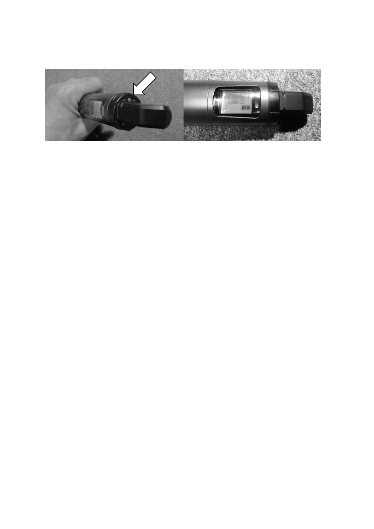
The microphone can now be switched on by pressing and holding the orange power
button until the display screen illuminates (as shown below)
Microphone power button (L) and display screen with ‘full power’ battery icon (R)
Once the microphone is powered up, the receiver unit at the AV control system will
illuminate yellow and display the same frequency as the microphone (ie. 613.000).
The microphone is switched off by pressing and holding the orange power button
until the display screen goes blank.


