Roadmaster VR500CS-BT Manuale utente

WELCOME!
Dear Customer,
CONGRATULATIONS. The VR500CS-BT MP3/CD Player with AM/FM Receiver,
USB Port and SD Card Slot, Electronic Anti-Shock (ESP) & Fold-down
Detachable Face, when used as described, will give you years of dependable
service in your car, truck, RV, or mini-van. We have taken numerous measures
in quality control to ensure that your product arrives in top condition and will
perform to your satisfaction. In the rare event that your VR500CS-BT MP3/CD
Player with AM/FM Receiver, USB Port and SD Card Slot, Electronic Anti-
Shock (ESP) & Fold-down Detachable Face,contains a damaged or missing
item, does not perform as specified, requires warranty service, or you have
an installation problem, DO NOT RETURN THIS PRODUCT TO THE STORE.
PLEASE CALL OUR TOLL FREE NUMBER FROM THE U.S.A. AND CANADA
1-800-445-1797 and ask to speak with a member of our technical service
team; or submit your questions by e-mail to customerservice@vr-3.com and
a member of our technical service team will respond by e-mail to your ques-
tions. Our in-house technical service team will expedite delivery of your part,
advise you on installation, or help troubleshoot a problem with you. If your
product needs warranty service, our technical service team representative will
help you obtain the fastest remedy possible under the warranty.
CONTENTS
Contents .......................................................................................................... 1
Precautions...................................................................................................... 2
Care of Discs ................................................................................................... 2
Flash Memory .................................................................................................. 2
Notes on Installation........................................................................................ 3
Tools & Supplies .............................................................................................. 3
Before You Install............................................................................................. 4
Installation (DIN Front Mount)......................................................................... 5
Installation (Vehicle's Brackets) ....................................................................... 6
Microphone...................................................................................................... 7
Wiring Connections ......................................................................................... 8
Location of the Controls.................................................................................. 9
Remote Control ............................................................................................. 10
Basic Operation ............................................................................................. 11
Bluetooth .................................................................................................. 12-13
Radio Operation............................................................................................. 14
CD Operation................................................................................................. 15
MP3/WMA Operation (CD) ............................................................................ 16
USB/SD Card Operation................................................................................ 17
Search Modes for MP3 & WMA Files............................................................ 18
AUX IN, RCA, & Subwoofer Control.............................................................. 19
Specifications ................................................................................................ 20
Warranty......................................................................................................... 21
1

PRECAUTIONS
• Handle the disc by its edge to keep
the disc clean. Do not touch the disc’s
surface.
• Do not use a CD with paste or ink
residue on it.
• Do not use CDs with labels or stickers
attached. The label may leave a sticky
residue when it begins to peel.
• Clean the discs with an optional clean-
ing cloth. Wipe each disc from the
center out.
Type of disc
CD, MP3, & WMA
Label on the disc
Recorded material
Audio only
Size of disc
12 cm
• Do not attempt to modify the unit.
• Modifying the unit will void the war-
ranty.
• Stop the vehicle before carrying out
any operation that could interfere with
your driving.
• Do not operate in extremely high or
low temperatures. The temperature
inside the vehicle should be between
32º F (0º C) and 100º F (37º C) before
turning on your unit.
• This unit will only play the following discs.
• This unit does not play files that have Digital Rights Management(DRM).
• If you have files that have Digital Rights Management(DRM) you should consult with
the vendor that you purchased files from for instructions on proper use.
2
FLASH MEMORY
The VR500CS-BT supports USB Flash Memory, Secure Digital Card (SD) and Multi
Media Card (MMC) of up to 1GB of memory.
We recommend you format your Flash Drive/SD Card in FAT32 format before sav-
ing any files. If you experience any compatibility problems, we recommend that you
contact the manufacturer of the Flash Drive/SD Card/Multi Media Card.
CARE OF DISCS

• Disconnect negative battery terminal before starting installation. Consult the vehi-
cle’s owner’s manual for proper instruction.
• The unit is designed for a 12Volt DC negative ground operation system only. Before
installing the unit, confirm that your vehicle is a 12Volt DC negative ground system.
• Be sure to connect the color coded leads according to the diagram. Incorrect con-
nections may cause the unit to malfunction or damage the vehicle’s electrical sys-
tem.
• Be sure to connect the negative (-) speaker leads to the negative (-) speaker termi-
nal. Never connect negative (-) speaker leads to chassis ground.
• The unit is only designed for use with 4 speakers. Do not combine output for use
with 2 speakers. Do not ground negative speaker leads to the chassis ground.
• Make sure all the connections are completely correct before turning on your unit.
• When replacing the fuse(s), the replacement must be of the same amperage as
shown on the fuse holder.
• Do not block vents or heater panels. Blocking them will cause heat to build up in-
side and may result in fire.
• After completing the installation and before operating the unit, reconnect the bat-
tery. Then press the (RES) button with a pointed object, such as a ball-point pen to
set the unit to its initial status.
NOTES ON INSTALLATION
TOOLS FOR INSTALLATION
• The 2 removal keys are supplied for removing the old unit and replacing with the
“VR500CS-BT”.
The following tools and supplies may also be needed for the installation:
TOOLS
• Phillips Screw-drivers
• Wire Stripper
• Wire Cutter
• Hammer
• Pencil
• Electrical Tape
• Electric Drill
SUPPLIES
• Machine Screws
• Crimp Connectors
• 14 Gauge Wire for Power Connections
• 14-16 Gauge Speaker Wires
The above are NOT INCLUDED with the VR500CS-BT and must be purchased seperately.
3
BEFORE YOU INSTALL
Automotive audio equipment installations can be troublesome at times, even to the most
experienced of installation technicians.
If you are not confident working with electrical wiring, removing and re-installing interior
panels, carpeting, dashboards or other components of your vehicle, please call your dealer
in order to have the unit professionally installed.
IMPORTANT: Remove the two transport screws from the top of the unit before installing.
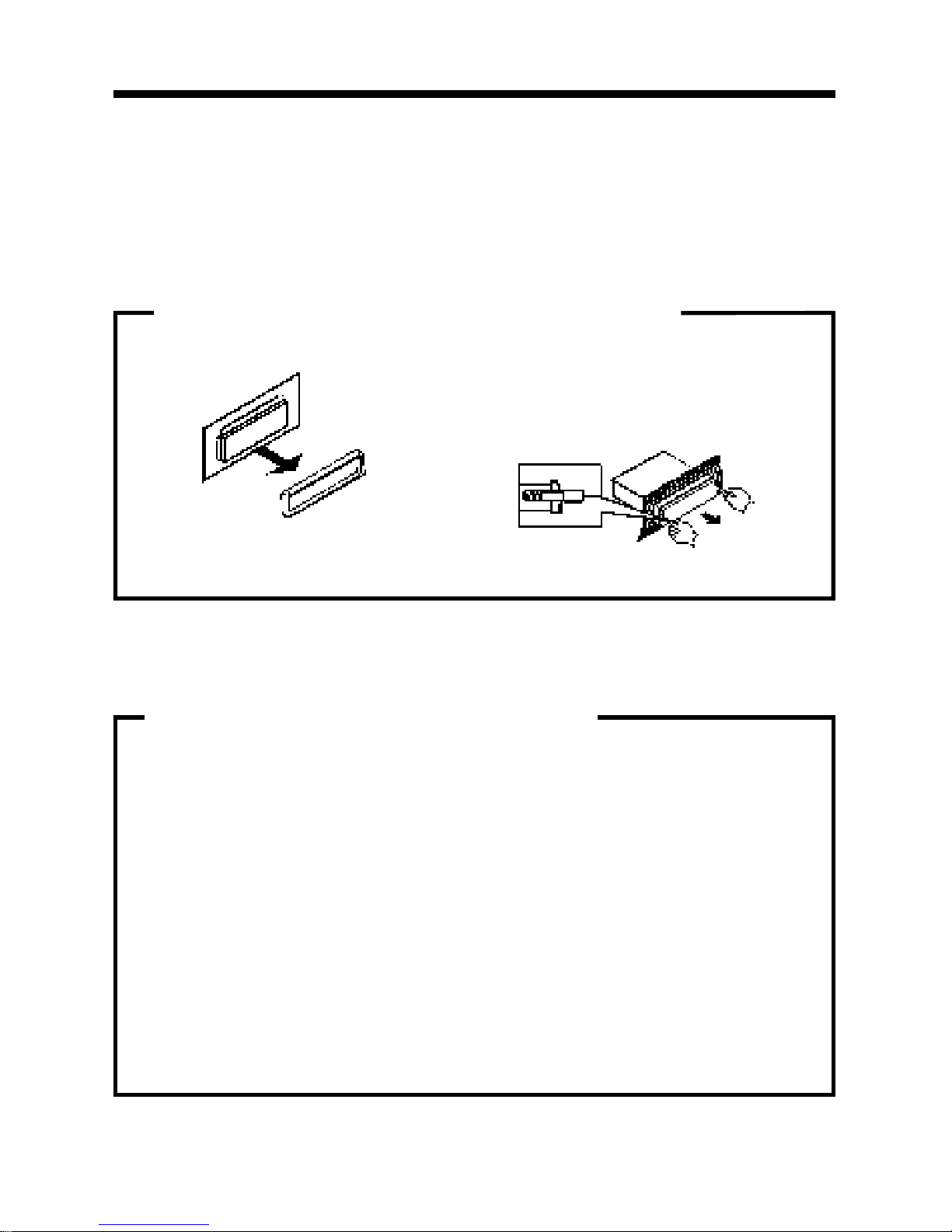
B. Insert the keys supplied with the old unit
into both sides of the unit as shown in fig-
ure below until they click. Pull to remove
the old unit from the dashboard.
DIN Front Mount Style
DO NOT DISCONNECT WIRES AT THIS TIME!
A. Remove the outer trim frame.
1. Remove the Old Unit from the Dashboard
A.
While the old unit is playing, discon-
nect the wires from one speaker.
B. Take a length of masking tape and
fold it around the wire so it forms a
flag.
C. On the masking tape mark the polar-
ity of the speaker wires (+ & - ), as
well as left or right, and front or rear.
D. Double check that you marked the
first speaker correctly by checking
that the speaker wires are the same
at the head unit.
E. Repeat this procedure for all of the
speakers.
F. Mark the power, ground, and any oth-
er wires also
.
2. Mark Polarity of the Speaker Wires
Marking the polarity of the speaker wires will make it easier to connect the existing
speakers to the DVD Head Unit.
Consult wiring diagram of existing head unit before disconnecting any wires. If a
wiring diagram is not available contact the manufacturer.
4
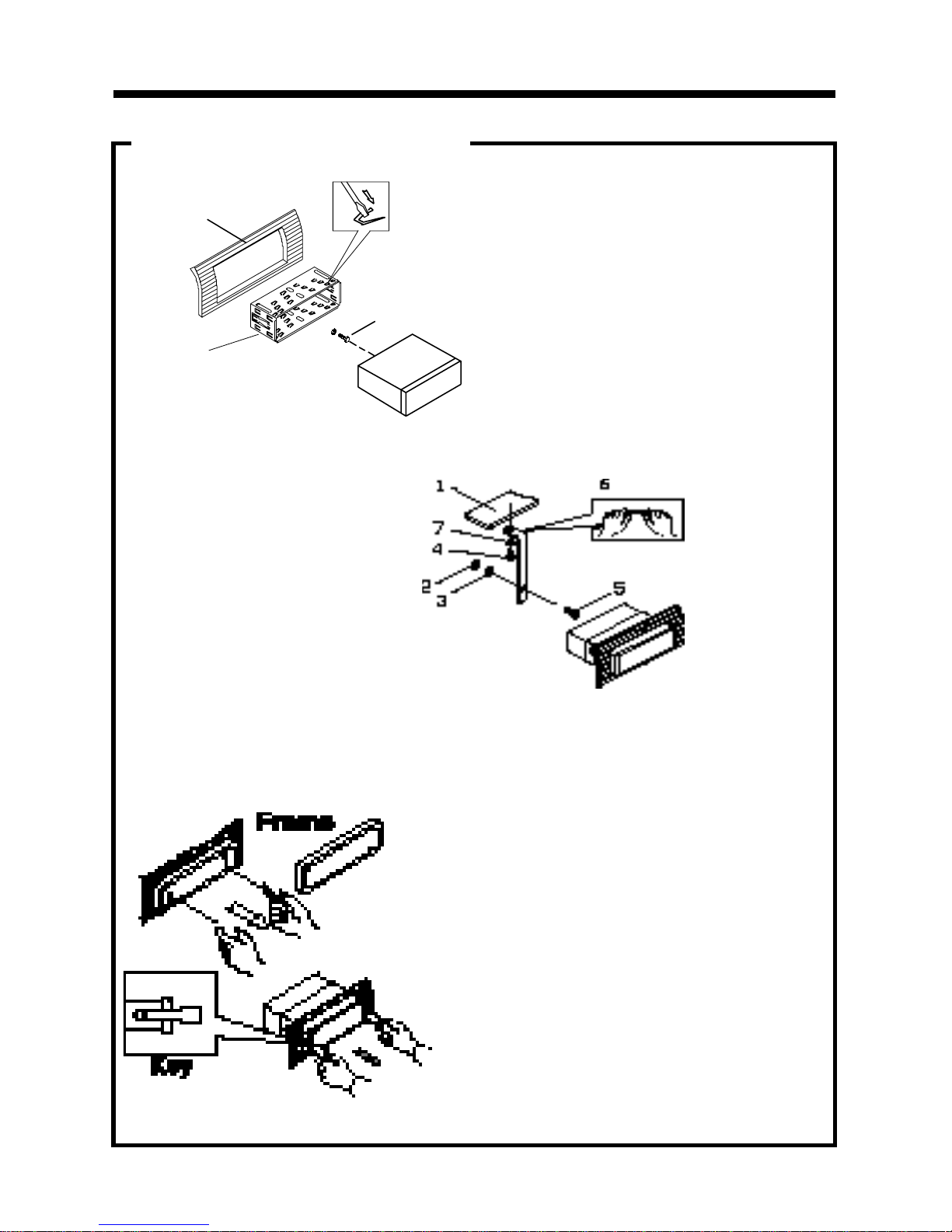
INSTALLTION
1. Dashboard
2. Nut (5mm)
3. Spring washer
4. Screw (5 x 25mm)
5. Screw
6. Strap
7. Plain washer
2. Mounting
Sleeve
3. Screw
1. Dashboard
Bend the tabs
to secure the
Mounting Sleeve
in the dashboard.
DIN FRONT-MOUNT (Method A)
After inserting the Mounting Sleeve
into the dashboard, select tabs on
top, bottom, and sides, then bend
them to secure the mounting sleeve
in the dash board.(Fig. 1)
Fig. 1
Fig. 2
Follow the diagram in Fig. 2
for installing the rear mounting
strap to the head unit. The rear
mounting strap will help keep
the head unit from moving
around inside the dashboard.
Insert fingers into the groove in the front of frame to remove it.
Insert the keys supplied with the unit in
the grooves on both sides. The unit can
be installed or removed from the dash-
board using these keys.(Fig. 3)
Fig. 3
5
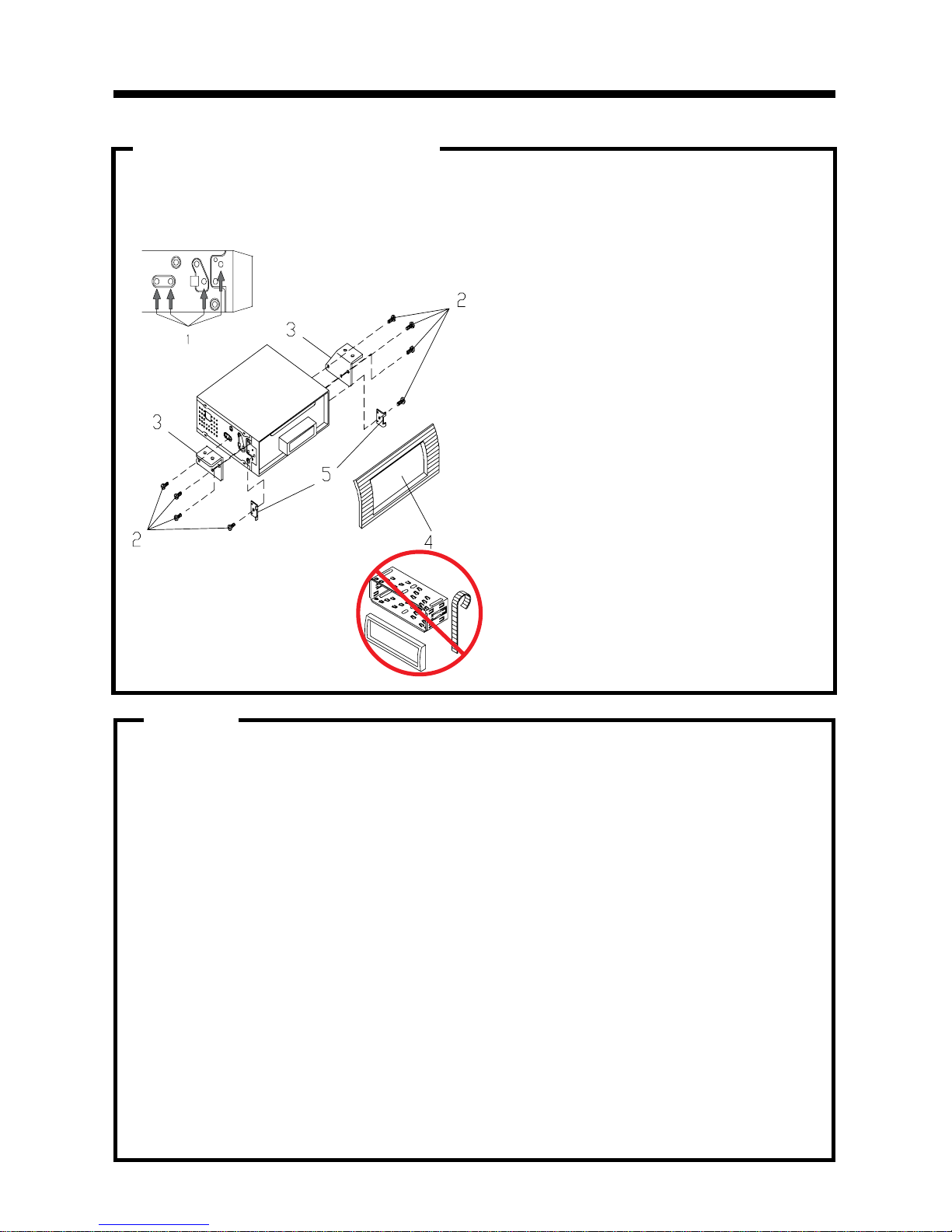
DIN REAR-MOUNT (Method B)
Installation using the screw holes on both sides of the unit.
1. Screw holes on the side of the unit.
2. Screws. Use either truss screws (5 x
8mm) or flush surface screws (4 x 8mm),
depending on the shape of the screw
holes in the bracket.
3. Vehicle’s Factory Mounting Bracket
4. Dashboard or Console
5. Hook (Remove this part)
Note: The mounting sleeve, outer trim
ring, and the mounting strap are not used
for this method of installation.
INSTALLATION
6
PARTS
2 Keys
1 Hex Nut
1 Mounting Sleeve (not shown)
2 Lock Washers
1 Sheet Metal Screw
1 Metal Support Strap
2 Flat Washers
1 Mounting Bolt
1 Faceplate Case
1 1/8" Stereo Cable
1 Remote Control
1 External Microphone (not
shown)
INSTALLATION
7
The VR500CS-BT has the ability to use two microphones. One microphone is built-in,
the other is a remote microphone.
NOTE: IT IS ALWAYS BEST TO INSTALL THE REMOTE MICROPHONE USING THE REAR “MIC
IN” JACK DURING THE INITAL INSTALLATION.
Built-In Microphone
The built-in microphone is located on the front left side of the unit. There is no setup re-
quired for this microphone and it is tuned to pick-up the voices of the front and rear seat
passengers.
Built-In Microphone (not visible)
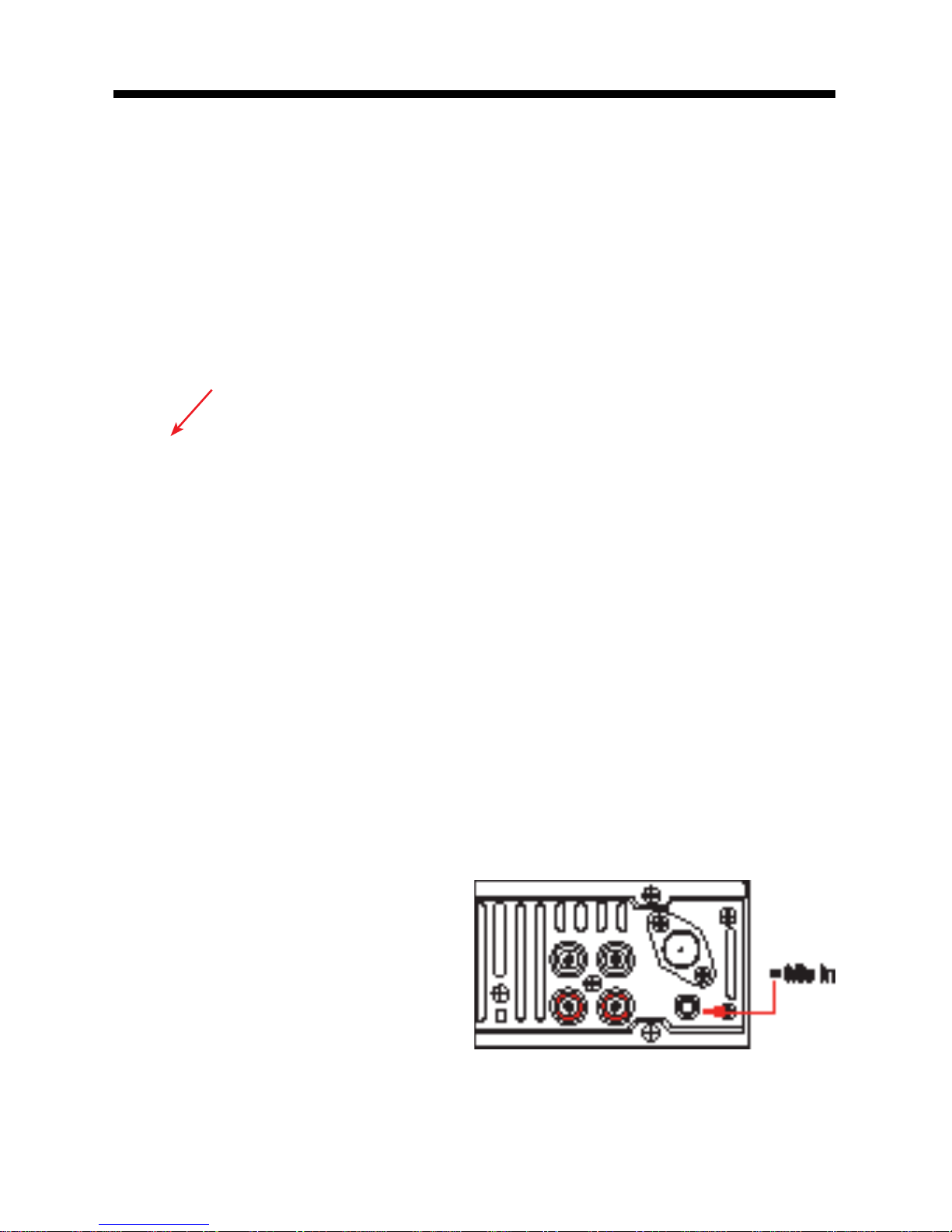
Rear Microphone Jack
The suppled microphone shall be used to ensure the sound quality of the driver’s voice.
Installation
The rear microphone jack is located on the rear of the unit. Insert the plug of the supplied
microphone into the microphone jack. Route the microphone and wire to the driver’s side
sun visor, rear view mirror, or other area near the driver.
MICROPHONES
Setting the Microphone Volume
1. Press the “PHONE” button.
2. Press and hold the Volume Knob until
you see “OUT NUM” on the LCD
3. Press the Volume Knob to cycle through
the menu to “TEL”.
4. Rotate the Volume Knob to set the vol-
ume of the microphone.
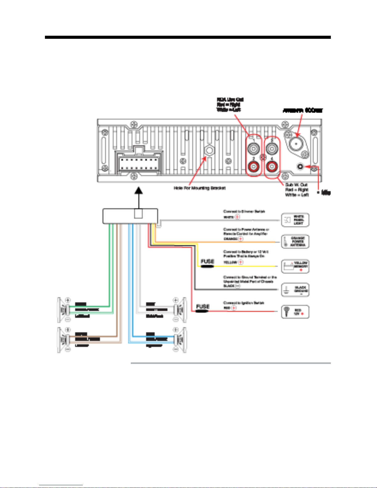
WIRING CONNECTIONS
Make sure you have good chassis ground. A good ground connection will eliminate
most electrical noise problems. A good chassis ground requires a tight connection to
the vehicle’s metal chassis. The area around the ground connection should be clean,
bare metal without rust, paint, plastic, dust, or dirt for a good electrical connection.
Follow the above wiring diagram to install
the head unit with new or existing speakers.
• This unit is designed for use with four (4)
speakers with an impedance between 4
Ohms to 8 Ohms.
• An impedance load of less than 4 Ohms
could damage the unit.
• Never bridge or combine the speaker wire
outputs. When not using four speakers, use
electrical tape to tape the ends of the unused
speaker outputs to prevent a short circuit.
• Never ground the negative speaker termi-
nals to chassis ground.
Speaker Wiring Notes
8

LOCATION OF THE CONTROLS
9
123 4 5678
1. SD/MMC Card Slot
2. Liquid Crystal Display (LCD)
3. CD Slot
4. BND•ID3 / ||
5. Previous Track/Fast Reverse
6. Power
7. Next Track/Fast Forward
8. Mode/Mute
9. Volume/SEL/Enter
10. Eject
11. Answer/ Green Phone
12. Hang up/ Red Phone
13. Remove Faceplate
14. Subwoofer/Pound Symbol
15. Scan/Star Symbol
16. FPS/Repeat
17. Stereo/No. 0
18. No. 9
19. No. 8
20. No. 7
21. UP 10/No. 6
22. Down 10/No.5
23. Random/ No. 4
24. No. 3
25. Intro/No. 2
26. Top/No.1
27. PHONE
28. Auxiliary Input
29. USB Port with Cover
30. Reset Button
31. A/E Switch
9 10 11
1213
1415
1617181920212223242526272829
31.30.
Indice
Altri manuali Roadmaster Ricevitore per auto


