RoboSense RS-Helios-1610 Manuale utente

RS-Helios-1610 User Manual
RS-Helios-1610

RS-Helios-1610 User Manual
I
Revision History
Issue
Modifications
Release Date
Edited by
1.0.0
Original issue
2022-08-31
PD

RS-Helios-1610 User Manual
II
Terminologies
MSOP
Main data Stream Output Protocol
DIFOP
Device Info Output Protocol
FOV
Field Of View
PTP
Precision Time Protocol
NTP
Network Time Protocol
GPS
Global Positioning System
UTC
Universal Time Coordinated
Wave_mode
Echo flag
Protocol
Protocol version number, 00 represents old version, 01 represents the latest
version
Temp
Sensor temperature information
Resv
Reserved data flag
Azimuth
LiDAR horizontal rotation angle
Timestamp
Time stamp which is used to record system time
Header
Frame header in protocol packet
Tail
Frame tail in protocol packet
Value
The decimal value obtained after conversion of the corresponding offset byte,
using big-endian mode, with the high bit in the front and the low bit in the
back

RS-Helios-1610 User Manual
III
Content
1 Safety Notices..............................................................................................................................................................1
2 Helios Series Products .............................................................................................................................................. 2
3 Product Appearance and Interface...................................................................................................................... 3
3.1 Product Appearance.................................................................................................................................... 3
3.2 Aviation Plug and Pin Definition.............................................................................................................. 3
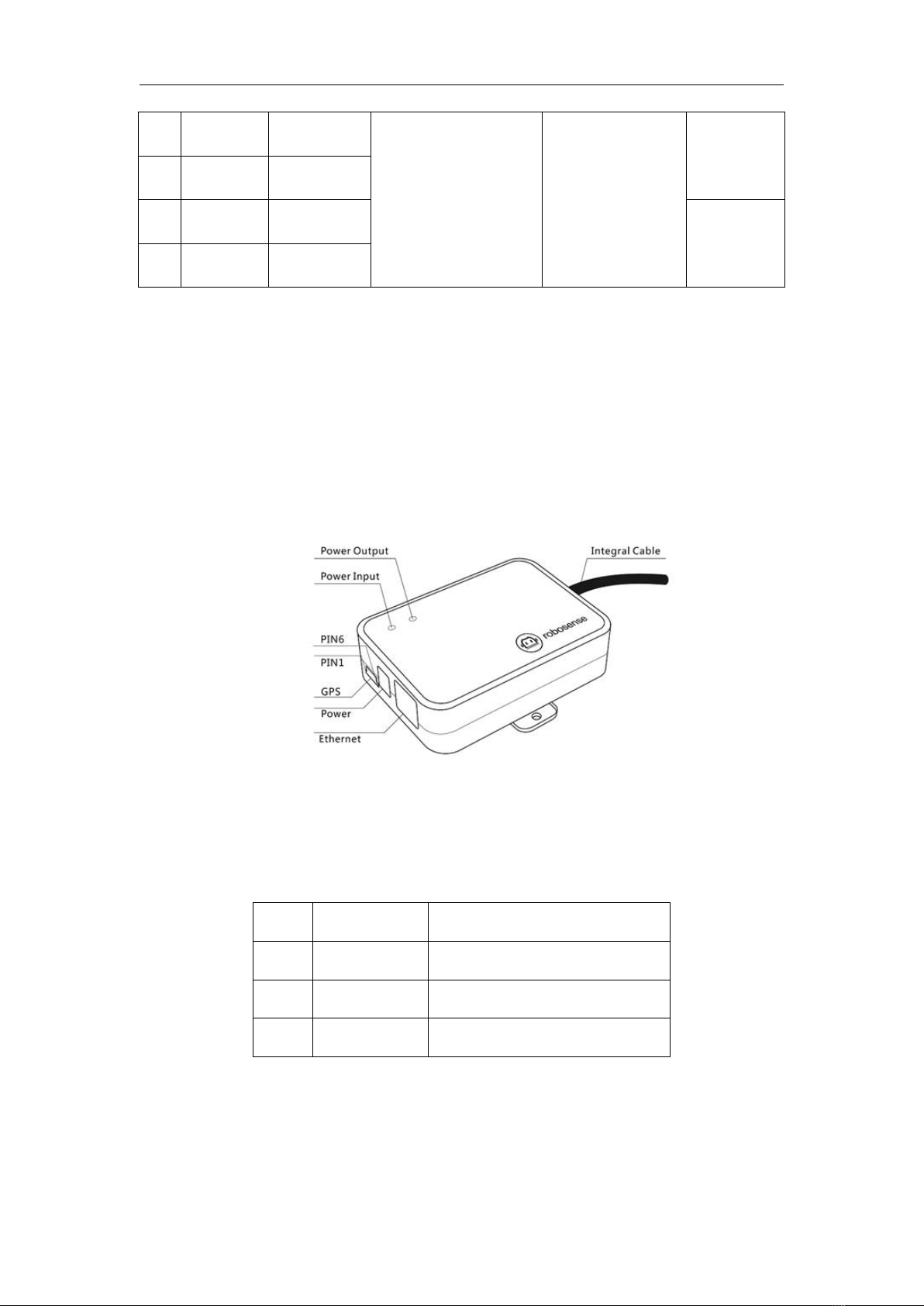
3.3 Interface Box...................................................................................................................................................4
4 Unboxing & Installation............................................................................................................................................6
4.1 Standard Package ..........................................................................................................................................6
4.2 Sensor Mounting...........................................................................................................................................6
4.3 Quick Connection ..........................................................................................................................................8
5 Sensor Specifications and Features...................................................................................................................10
5.1 Sensor Specification..................................................................................................................................10
5.1.1 Parameters......................................................................................................................................10
5.2 Point Cloud Display....................................................................................................................................12
5.2.1 Coordinate Mapping....................................................................................................................12
5.3 Reflectivity....................................................................................................................................................12
5.4 Laser Return Modes .................................................................................................................................. 13
5.4.1 Principle of Laser Return Modes............................................................................................. 13
5.4.2 Return Mode Flag.........................................................................................................................14
5.5 Phase Locking.............................................................................................................................................. 14
5.6 Time Synchronization............................................................................................................................... 15
5.6.1 GPS Time Synchronization.........................................................................................................15
5.6.2 The Use of GPS for Time Synchronization............................................................................15
5.6.3 PTP Time Synchronization......................................................................................................... 16
5.6.4 PTP wiring Method.......................................................................................................................17
6 Communication Protocol...................................................................................................................................... 17
6.1 MSOP and DIFOP........................................................................................................................................18
6.2 Main Data Stream Output Protocol(MSOP)............................................................................... 18
6.2.1 Header ..............................................................................................................................................18
6.2.2 Data Blocks......................................................................................................................................19
6.2.3 Tail......................................................................................................................................................21
6.3 Device Info Output Protocol(DIFOP).............................................................................................22
7 Vertical Angles and Precision Point Timing Calculation ..............................................................................24
7.1 Channel Number and Vertical Angle ................................................................................................... 24
7.2 Exact Point Timing Calculation.............................................................................................................. 24
8 Troubleshooting ....................................................................................................................................................... 26
Appendix A Web Interface....................................................................................................................................... 28
A.1 Device Screen..............................................................................................................................................28
A.2 Web Interface for Sensor Setting ......................................................................................................... 28
A.3 Diagnostic Screen ...................................................................................................................................... 31
A.4 System Screen.............................................................................................................................................32
Appendix B Information Registers.........................................................................................................................34

RS-Helios-1610 User Manual
IV
B.1 Motor Speed (MOT_SPD) ........................................................................................................................34
B.2 Ethernet(ETH).......................................................................................................................................34
B.3 FOV Setting(FOV_SET)....................................................................................................................... 35
B.4 Motor Phase Offset (MOT_PHASE)......................................................................................................35
B.5 Top Board Firmware Version (TOP_FRM).......................................................................................... 35
B.6 Bottom Board Firmware Version(BOT_FRM)....................................................................................36
B.7 Motor Firmware Version(MOT_FRM)................................................................................................. 36
B.8 Software Version(SOF_FRM)..................................................................................................................36
B.9 Corrected Vertical Angle(COR_VERT_ANG) ...................................................................................... 37
B.10 Corrected Horizontal Angle(COR_HOR_ANG)............................................................................ 38
B.11 Serial Number(SN)............................................................................................................................... 39
B.12 Software Version(SOFTWARE_VER)........................................................................................... 39
B.13 UTC Time(UTC_TIME)......................................................................................................................39
B.14 STATUS(STATUS).................................................................................................................................40
B.15 Fault Diagnosis(FALT_DIGS)...........................................................................................................40
B.16 GPRMC Data Packet-ASCII Code Data Type.................................................................................... 42
Appendix C RSView.....................................................................................................................................................43
C.1 Software Features......................................................................................................................................43
C.2 Install RSView.............................................................................................................................................. 43
C.3 Set Up Network.......................................................................................................................................... 44
C.4 Visualize Streaming Sensor Data.......................................................................................................... 44
C.5 Capture Streaming Sensor Data to PCAP File ...................................................................................45
C.6 Replay PCAP File .........................................................................................................................................45
C.7 Set RSView Data Port................................................................................................................................ 48
Appendix D RS-Helios ROS&ROS2 Package........................................................................................................ 49
D.1 Install Software...........................................................................................................................................49
D.2 Download & Compile RoboSense LiDAR Driver Package............................................................. 49
D.3 Configure PC IP........................................................................................................................................... 50
D.4 Real Time Display.......................................................................................................................................50
D.5 View Offline Data.......................................................................................................................................51
Appendix E Mechanical Drawings......................................................................................................................... 52
Appendix F Sensor Cleaning .................................................................................................................................... 53
F.1 Attention........................................................................................................................................................53
F.2 Required Materials.....................................................................................................................................53
F.3 Cleaning Method ........................................................................................................................................ 53

RS-Helios-1610 User Manual
V
1. Manufacturer Information
Suteng Innovation Technology Co., Ltd. (RoboSense)
Building 9, Block 2, Zhongguan Honghualing Industry Southern District, 1213 Liuxian Avenue,
Taoyuan Street, Nanshan District, Shenzhen, ChinaLandline: 0755-86325830
Mobile Phone: +86 15338772453(Marketing & Sales Cooperation)
Email: service@robosense.cn
Working hours from Monday to Friday 09:00-18:00(GMT/UTC +8)
2 Disclaimer of Liability
This manual is protected by copyright. Any rights arising from this copyright are owned by
RoboSense. Reproduction of this manual or part of the manual is only permitted within the legal
scope of the copyright law. Without obtaining any authorization, this document shall not be
abridged or translated. The trademarks mentioned in this document are the property of their
respective owners. RoboSense reserves all rights.
3 Certifications
Note:
This manual is updated from time to time without prior notice, to get the latest version, please
visit RoboSense company website to download or contact the RoboSense Technical Support or
Sales.

RS-Helios-1610 User Manual
1
1 Safety Notices
To avoid risks of accidents, damage to sensor or violating of your product warranty, please read
and follow the instructions in this manual carefully before operating the product.
Laser Safety
This product meets the following standards for laser products:
IEC 60825-1:2014;
Please pay attention to the overheating sign on the LiDAR surface to avoid a hot LiDAR
surface that may lead to sensor failure or undesirable consequences.
Retain Instructions - The safety and operating instructions should be retained for future
reference.
Heed Warnings - All warnings on the product and in the operating instructions should be
adhered to.
Servicing – Except for what’s described in this manual, the sensor has no field serviceable
parts. For servicing, please contact RoboSense sales or the authorized distributors.

RS-Helios-1610 User Manual
2
2 Helios Series Products
No.
Model
Number of Channels
FOV
Remark
1
RS-Helios-5515
32
-55°~+15°
Wide FOV
2
RS-Helios-1615
32
-16°~+15°
Uniform 1° Vertical Resolution
3
RS-Helios-1610
32
-16°~+10°
up to 0.5°
4
RS-Helios-16P
16
-15°~+15°
Uniform 2° Vertical Resolution
This manual is for the RS-Helios-1610 product.

RS-Helios-1610 User Manual
3
3 Product Appearance and Interface
3.1 Product Appearance
Figure 1 LiDAR Coordinate and Rotation Direction
3.2 Aviation Plug and Pin Definition
RS-Helios-1610 has an aviation plug attached to the bottom of the LiDAR, the definitions of the
specific pins of the aviation plug are as shown in the table below:
Pin
Color
Function
Operating Voltage Range
Working Current
Other
1
Red
PWR
9~32V
1.2A
/
2
Black
PWR
3
Gray
GND
/
1.2A
4
Blue
GND
5
Brown
GPS_PPS
3~15V
/
6
White
GPS_GPRMC
-15V~+15V
Aviation plug interface side

RS-Helios-1610 User Manual
4
Figure 2 Definition of Pins of Aviation Plug
3.3 Interface Box
Your RS-Helios-1610 comes with an Interface Box, which has 2 LED lights and provides convenient
connections to power, RJ45 Ethernet, and GPS. (The length of the integrated cable attached to
the Interface Box of the aviation plug version LiDAR is 3 meters, for other cable lengths, please
contact RoboSense technical support).
Figure 3 Definition of Interface Box Ports
Specifications of Interface Box ports:
Table 1 Interface Box Port Specification
No.
Port
Specification
1
Power Input
Standard DC 5.5-2.1 connector
2
Network
Standard RJ45 Ethernet connector
3
GPS timing
SH1.0-6P Female connector
3.3.1 Power
The power supply interface on the Interface Box is a standard DC 5.5-2.1 connector.
There are 2 LEDs in the Interface Box: when the power input is normal, the red LED lights up;
7
Purple
SYNC_OUT1
0~3.3V
8
Green
SYNC_OUT2
9
Orange
TRD_N
Twisted Pair
10
Yellow
TRD_P
Indice
Altri manuali RoboSense Robotica


