Rohde & Schwarz SpycerBox Cell Manuale operativo

Version 1.0.1
Rohde & Schwarz DVS GmbH
Krepenstraße 8
30165 Hannover
Germany
http://www.dvs.de
Copyright © 2015 by Rohde & Schwarz DVS GmbH, Hanover. All rights reserved.
R&S® is a registered trademark of Rohde & Schwarz GmbH & Co. KG. DVS and Spycer are registered trademarks of Rohde & Schwarz
DVS GmbH.
Any product and/or company names mentioned in this documentation may be trademarks or registered trademarks of their respective
owners and as such are subject to the usual statutory provisions.
1Rohde & Schwarz DVS GmbH
SpycerBox Cell
Important Information
Before you can start working with the system, you have to insert all hard disks into
their respective places on the hard disk tray. The hard disks carry numbers indicating
whether a hard disk should be put into the hard disk tray on top (Top: T0, ..., T14) or
into the second hard disk tray at the bottom (Bottom: B0, ..., B14). Before you can
pull out a hard disk tray, you first have to remove the faceplate. All is described in
this document.
1.1 Contents
Read the information first
The hard disks and/or the system might be damaged if you do not carry out all
necessary tasks properly.
Read the information below first, before attempting to assemble the
hard disks or before you carry out any task with the SpycerBox Cell.
Read the “SpycerBox Cell Hardware Guide“ as well.
This document deals with the following topics:
Removing the Faceplate on page 2
Assembling the Hard Disks on page 3
Fastening the Faceplate on page 6

2
SpycerBox Cell - Important Information
Rohde & Schwarz DVS GmbH
1.2 Removing the Faceplate
To access one of the hard disk trays, you just have to remove the faceplate:
Figure 1: Removing the faceplate
To remove the faceplate, perform the following steps:
1. Press the darker metal button on the right side of the faceplate and keep it
pressed.
2. When standing right in front of the SpycerBox Cell, pull the faceplate with
moderate but intense strength from the right side to your direction.
3. Take the faceplate out of its fastening on the left side.
In the next step you can then insert the hard disks in their places on the hard disk
trays (see section “Assembling the Hard Disks” on page 3).
1
2

3
SpycerBox Cell - Important Information
Rohde & Schwarz DVS GmbH
1.3 Assembling the Hard Disks
Assembling the hard disks is easy as you simply have to insert them in their places
in the correct order on the hard disk tray. Perform the following to assemble the hard
disks in the system:
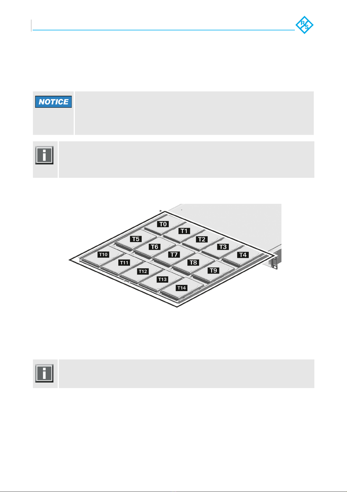
You have to assemble the hard disks in the following order:
Figure 2: Order of hard disks in the system
The order of hard disk on the second hard disk array at the bottom is the same as in
the figure above, except the letter ‘B‘ instead of the letter ‘T‘.
1. Unpack the hard disks you have received from R&S DVS.
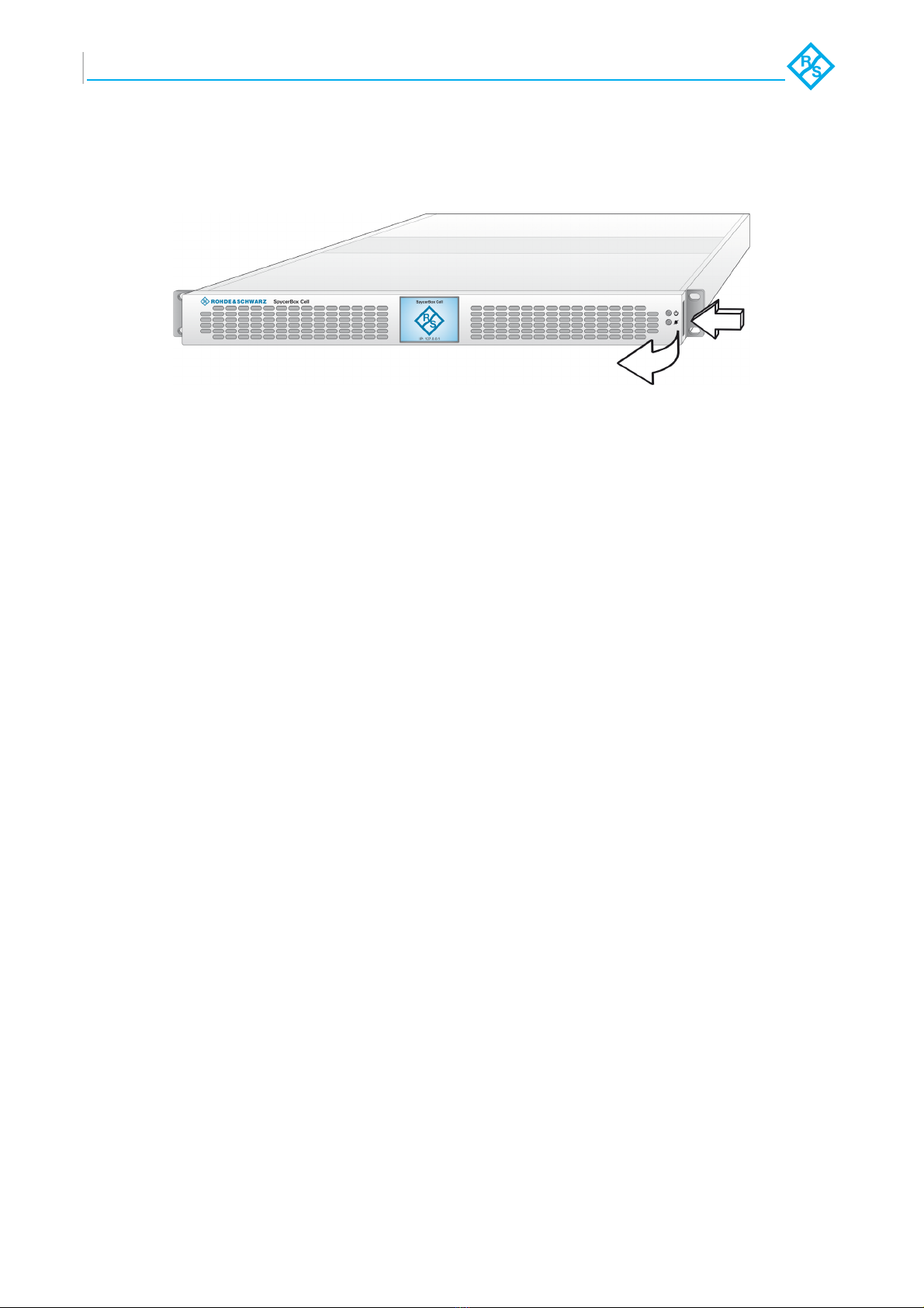
2. When standing right in front of the system, you have to cautiously slide the
hard disk in its place on the hard disk tray.
For this take the lever of the hard disk and then insert the hard disk cautiously
in place, in the direction away from your position and down, as shown in the
following figure:
Incorrect handling of the hard disks
Significant environmental changes, for example, altitude, voltage, temperature,
shock, vibration, etc., can damage a hard disk.
Handle hard disks with great care.
It is recommended to start with the second hard disk tray at the bottom and insert
the hard disks B0, ..., B14. Then slide the hard disk tray back into the system, pull out
the first hard disk tray and insert the hard disks T0, ..., T14 into their places as shown
in the following.
Please heed the respective numbering on the hard disks and therefore their position
in the hard disk tray. Furthermore, please heed the position of the interface on the
hard disk and on the hard disk tray which have to match.

4
SpycerBox Cell - Important Information
Rohde & Schwarz DVS GmbH
Figure 3: Inserting the hard disk
3. Then simply move the lever back down.
Figure 4: Moving down the lever
The disk carrier of the replaced disk should be level with the others of the array.

5
SpycerBox Cell - Important Information
Rohde & Schwarz DVS GmbH
4. Cautiously push the disk tray back into the SpycerBox Cell.
Figure 5: Pushing the disk tray back in
5. Fasten the faceplate as described in section “Fastening the Faceplate” on
page 6.
When you start to work with the system after having fastened the faceplate as de-
scribed in section “Fastening the Faceplate” on page 6, the LEDs on the hard disks
will show you their state and therefore a successful assembly. Use the SAN Remo
configuration management software to check if assembling the hard disks has been
successfully completed as well. For this, see the „SAN Remo Configuration Manage-
ment“ supplement.

6
SpycerBox Cell - Important Information
Rohde & Schwarz DVS GmbH
1.4 Fastening the Faceplate
As the last step, before you can start to work with the SpycerBox Cell, you have to
fasten the faceplate to the R&S DVS system again. For this perform the following:
1. Simply put the faceplate back into its fastening at the left side (see section
“Removing the Faceplate” on page 2).
2. Press the faceplate with moderate but intense strength until it snaps into its
fastening at the right side.
With this, the task of fastening the faceplate is finished. You can then begin working
with the SpycerBox Cell as described in the “SpycerBox Cell Hardware Guide“.
When you switch on the system, the R&S DVS logo in the middle of the faceplate
will be illuminated.
Indice


