Ross Synergy Series Manuale utente

Ross Video Limited
Synergy Display Replacement
Installation Guide
DIGITAL PRODUCTION SWITCHER
SERIES

2
Synergy Display Replacement Installation Guide
• Ross Part Number: 4800DR-350-01
• Release Date: March 22, 2011. Printed in Canada.
The information contained in this guide is subject to change without notice or
obligation.
Copyright
© 2011 Ross Video Limited. All rights reserved.
Contents of this publication may not be reproduced in any form without the
written permission of Ross Video Limited. Reproduction or reverse engineering
of copyrighted software is prohibited.
Patents
This product is protected by the following US Patents: 4,205,346; 5,115,314;
5,280,346; 5,561,404; 7,034,886; 7,508,455; 7,602,446; 7,834,886. This
product is protected by the following Canadian Patents: 2039277; 1237518;
1127289. Other patents pending.
Notice
The material in this guide is furnished for informational use only. It is subject to
change without notice and should not be construed as commitment by Ross
Video Limited. Ross Video Limited assumes no responsibility or liability for
errors or inaccuracies that may appear in this guide.
Trademarks
• is a trademark of Ross Video Limited.
• Ross, ROSS, ROSS®, MLE, Vision, and Octane are registered or
unregistered trademarks of Ross Video Limited.
•All other product names and any registered and unregistered
trademarks mentioned in this guide are used for identification
purposes only and remain the exclusive property of their
respective owners.

3
Important Regulatory and Safety Notices to Service
Personnel
Before using this product and associated equipment, refer to the “Important
Safety Instructions” listed here and in the front of the Vision Engineering
Manual, to avoid personnel injury and to prevent product damage.
Products may require specific equipment, and/or installation procedures to be
carried out to satisfy certain regulatory compliance requirements. Notices have
been included in these publications to call attention to these specific
requirements.
Important Safety Instructions
Use only manufacturer approved Power Supplies and Power Cords supplied
with this product.
The power supply adapter(s) included with this product use a protective earth
connection to reduce the risk of electrical shock to the operator and or service
personnel. A grounding conductor in the equipment's supply cord provides this
protective earth connection and must be reliably connected to a facilities
protective earth.
Do not defeat safety purpose of the polarized or grounding-type plug. A
polarized plug has two blades with one wider than the other. A grounding type
plug has two blades and a third grounding prong. The third prong is provided for
your safety. If the provided plug does not fit in to your outlet, consult an
electrician for replacement of the obsolete outlet.
Protect the product’s power cord(s) and replace any cord(s) which shows signs
of physical damage or ware.
The product's power supply cord(s) is (are) used as a means to disconnect the
power supply from the AC Mains. Ensure either the appliance inlet or the mains
plug of the power supply cord, remains readily operable.
This product is designed for Indoor Use:
“WARNING - TO REDUCE THE RISK OF FIRE OR ELECTRIC SHOCK,
DO NOT EXPOSE THIS APPERATUS TO RAIN OR MOISTURE”.
General Handling Guidelines
• Careful handling, using proper ESD precautions, must be observed.
• Power down the system before PCB removal.
4
ESD Susceptibility — Avoid handling the switcher circuit
boards in high static environments such as carpeted areas, and
when synthetic fiber clothing is worn. Touch the frame to
dissipate static charge before removing boards from the frame,
and exercise proper grounding precautions when working on
circuit boards.
Environmental Information
The equipment that you purchased required the extraction and use
of natural resources for its production. It may contain hazardous
substances that could impact health and the environment.
To avoid the potential release of those substances into the environment and to
diminish the need for the extraction of natural resources, Ross Video encourages
you to use the appropriate take-back systems. These systems will reuse or
recycle most of the materials from your end-of-life equipment in an
environmentally friendly and health conscious manner.
The crossed-out wheeled bin symbol invites you to use these systems.
If you need more information on the collection, reuse, and recycling systems,
please contact your local or regional waste administration.
You can also contact Ross Video for more information on the environmental
performances of our products.
Package Contents • 5
Package Contents
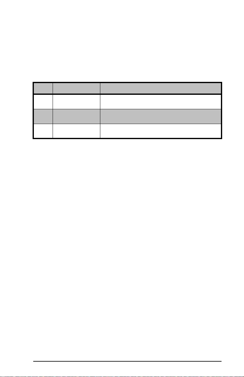
The contents of the Synergy Display Replacement kit are listed below. If any
items are missing, or damaged, contact Ross Video Technical Support.
Qty Part# Item
1 70-00124 Display
130-00104 3-Pin Display Power Connector Cap
1 4000ER-033-01 EEPROM U62, Issue 7
6 • Synergy Display Replacement
Synergy Display Replacement
To install the new display in the control panel, you must power down the control
panel and remove the old display, install the cap on the 3-pin power connector,
and install the new display, and set the contrast for the new display.
Once the new display has been installed, you must upgrade the EEPROM
installed on the control panel CPU board.
Removing the Synergy Display
To remove the display, you will need a pair of small needle-nose pliers and a
Phillips screw driver.
1. Power down the control panel. The frame can remain on during this
procedure. Refer to your switcher documentation for information on
shutting down the control panel.
2. Unplug the Primary and Redundant (if installed) power from the
control panel.
Warning Hazardous Voltage — Hazardous voltages are
present in the control panel as long as any of the power supplies
are connected to the AC power.
3. Lift up on the control panel lid to gain access to the control panel tub.
4. Identify the board (Function Switch Board) that the 3-Pin Display
Power and 15-Pin Data Cables from the display connect to. It is
located behind the F1-F6 buttons inside the control panel. The name
and shape of this board is different, depending on the control panel
you have.
•Synergy 2 — Function Switch Board (4317A-037)
•Synergy 3 — Function Switch Board (4735A-037)
•Synergy 4 — Function Switch Board (4735A-037)
5. Locate the 15-Pin Data Cable going from the display to the Function
Switch Board. Where the cable connects to the display, take note of
the orientation of the connector with relation to pin 1 screened on the
board. You must install the cable onto the new display in the same
way.
6. Disconnect the 15-Pin Data Cable from the connector on the display.
Synergy Display Replacement • 7
7. Use a pair of small needle-nose pliers to disconnect the 3-Pin Display
Power Cable from the power connector on the Function Switch
Board.
8. Remove the retaining screws from each corner of the display and put
them in a safe place. You will need them to install the new display.
9. Carefully remove the display from the inside of the control panel.
Installing the Synergy Display
To install the new display, you will need a pair of small needle-nose pliers and a
Phillips screw driver.
1. Use a pair of small needle-nose pliers to install the 3-Pin Display
Power Connector Cap (30-00104) into the power connector on the
Function Switch Board. The new display does not require a separate
power connector.
Warning Hazardous Voltage — You must install the 3-Pin
Power Connector Cap to protect the live power pins in the
connector. Failure to do so could result in personal injury or
damage to equipment.
2. Carefully install the new display into the hole that the old display was
removed from.
3. Install the retaining screws into each corner of the display. Do not
over-tighten the screws.
4. Connect the 15-Pin Data Cable to the data connector on the display.
Ensure that the orientation of the connector, with relation to pin 1, is
the same as it was when the cable was connected to the old display.
Caution — You must install the 15-Pin Data Cable onto the new display
in the same orientation as it was removed from the old display. Installing
the cable incorrectly could damage the display and the switcher.
8 • Control Panel EEPROM Upgrade
Control Panel EEPROM Upgrade
To upgrade the EEPROM on the control panel CPU Board, you must open the
CPU enclosure in the control panel, remove the old EEPROM, and install the
new EEPROM in the same socket.
Upgrading the Control Panel EEPROM
To upgrade the EEPROM, you will need a DIP Extraction Tool and a Phillips
screw driver.
1. Power down the control panel. The frame can remain on during this
procedure. Refer to your switcher documentation for information on
shutting down the control panel.
2. Unplug the Primary and Redundant (if installed) power from the
control panel.
Warning Hazardous Voltage — Hazardous voltages are
present in the control panel as long as any of the power supplies
are connected to the AC power.
3. Lift up on the control panel lid to gain access to the control panel tub.
4. Remove the screws securing the top of the CPU Enclosure inside the
control panel tub and remove the top.
5. On the Panel CPU Board (4000AR-033), locate the EEPROM U62
(4000ER-033-01). Note the orientation of the EEPROM in the
socket. The new EEPROM will have to be installed in the same
orientation.
6. Use the DIP Extraction Tool to remove the old EEPROM U62
(4000ER-033-01) from the socket.
Caution — Refer to the documentation that came with your DIP
Extraction Tool for information on proper use of this tool. Improper use of
the tool could damage the board, the socket, or both.
7. Install the new EEPROM U62 into the socket in the same orientation
as the old EEPROM.
8. Locate the J7 jumper at the front of the Panel CPU Board and move
the jumper cap from DOWN (default) to UP.
9. Re-install the top of the CPU Enclosure and re-connect the power
supplies to the control panel.

Setting the Display Contrast • 9
Setting the Display Contrast
The default contrast of the new display is different than the old display. When
the new display is installed, you must adjust the contrast so that the menus on
the display are visible.
1. Press HOME BMore BF6 (Setup) BF1 (Display) BF1
(Large Display).
2. Use the middle (Contrast) knob to select 70.0%, or the contrast that
best works for you.

10 • Setting the Display Contrast
Notes
Questo manuale è adatto per i seguenti modelli
1
Indice
Altri manuali Ross Monitor


