ROTA MASTER RM3000 Manuale utente

1
ROTA MASTER • RM3000
© Bernhard and Company Limited
ROTA MASTER • RM3000
Please read this manual carefully before using the Rota Master.
This manual should be kept in a safe place so that it can be used for future reference.
ROTA MASTER
RM3000 Automatic Rotary Blade Grinder
User’s Guide &
Instruction Manual

2
ROTA MASTER • RM3000
© Bernhard and Company Limited
ROTA MASTER
Contents
BERNHARD AND COMPANY LTD
Bilton Road • Rugby • England • CV22 7DT
Tel +44 1788 811600 • Fax +44 1788 812640
Email: info@bernhard.co.uk
USA Toll Free 1-888 GRIND IT (
1-888 474 6348)
RM3000 Automatic Rotary Blade Grinder
You are now the owner/operator of a Bernhard’s Rota Master (RM3000) which,
if cared for and operated correctly, will give you years of good service.
This manual will enable you to obtain the best results from your RM3000 so please
read it thoroughly before using your machine.
If you have any service or operational problems contact your distributor,
or phone our
Technical Helpline (USA only) – 1-888 474 6348
or
Bernhard and Company Ltd, England – (+44) 1788 811600
or email
use the technical support feedback form on our web site
www.expressdual.com or www.bernhard.co.uk
Overview 3
Safety 4
Installation 5
Setting Up 7
Grinding the Blade 13
Blade Balancing 16
Cleaning 17
Part Numbers and Reference Diagrams 18
Wiring Diagram 24
RM3000_2004/03

3
ROTA MASTER • RM3000
© Bernhard and Company Limited
Adjusts mist coolant ow rate
Index stop
Adjusts
motor height
and angle
Spark/debris
scoop
‘Quick’ nut
Index stop
Traverse
stop
Locating
cone
Blade
balancer
Spark/debris scoop
mount point
Spark/debris
scoop mount
point
Grind (clockwise)
Left side of stone
Grind (anti-clockwise)
Right side of stone
Task light
(on/off)
Vacuum
(on/off)
Emergency
stop
Auto traverse
(on/off)
Fuses
Anti-rotate
stop
Adjusts blade angle to stone

4
ROTA MASTER • RM3000
© Bernhard and Company Limited
1.1 This machine is primarily designed for safe and accurate grinding of rotary mower blades.
It should not be used for any other purpose.
1.2 This machine should be installed, operated and maintained by only competent personnel.
1.3 Before carrying out any work on the machine, other than actual grinding, isolate the
electrical power supply
1.4 Always operate the machine with the guards in place. Always wear adequate eye, ear
and breathing protection.
1.5 Only use grinding wheels recommended for this type of grinding unit, rated at the speed
specied on the grinder identication plate.
1.6 Never leave rags or tools on the machine, or allow combustible materials to accumulate
around the machine.
1.7 Always ensure that the unit to be ground is securely mounted on the machine with no
loose components.
1.8 Always ensure that all electrical connections are sound, with cables safely routed.
1.9 Stay alert. Wear suitable clothing. Never operate the machine when tired or under the
inuence of alcohol or drugs.
1. Safety
5
ROTA MASTER • RM3000
© Bernhard and Company Limited
2. Installation
End cap is swapped to
opposite end if grinding on
right hand side of stone
2.3 Connect to a 230-240v 50 Hz mains power supply, OR,
In the USA, to a 220v 60 Hz mains supply with a 30A breaker.
NOTE: (Pre. Oct. 2001 Rotamaster)
USA/ Canada units are connected to 110-120v mains supply.
Motor, vacuum and control gear are 220v.Power is stepped up from 110v to 220v by
the transformer tted into the base of the machine cabinet.
Fig: 2.2
2.1 Having removed the Rota-Master from its packing, the unit should be positioned in a well
lit area, with good ventilation, on a at and solid oor. If required the unit can be bolted
to the oor for added stability.
2.2 Check that the vacuum unit in the cabinet base is turned on (secondary switch on the
vac’ unit) and that the hose is connected to the spark debris collector on the appropriate
side of the grinding head.

6
ROTA MASTER • RM3000
© Bernhard and Company Limited
2. Installation (Continued)
Air
regulator
Fig: 2.4
Air supply
connector
Cross (in-feed) of carriage
2.5 Fill the coolant reservoir with
clean water (or water with
a capful of rust inhibitor
added).
Fig: 2.5 Interior of cabinet:
Coolant and vacuum unit
2.4 Connect to the workshop air supply, set regulator (on right hand side control panel) to
85 – 90 psi (~ 6 bar)

7
ROTA MASTER • RM3000
© Bernhard and Company Limited
3. Setting Up
Clockwise Counter-clockwise
3.2.3 Place the blade support over the spigots on the appropriate side of the carriage (so that
the front of the blade should be around ” (6mm) clear of the front of the grind stone when
the carriage is fully out)
Fig: 3.2.2
Fig: 3.2.3
Spigot
3.1 Blade Preparation
3.1.1 Clean the blade. Remove dirt, debris and surface rust from the cutting area of the blade.
Typically use a stiff wire brush.
3.1.2 Carefully examine the blade for cracks. If any cracks are observed SCRAP THE BLADE
– DO NOT ATTEMPT TO SHARPEN IT as cracks can lead to breakages, ying debris
and potential injury.
3.1.3 Check the blade for straightness. If a blade is bent DO NOT SHARPEN IT. DO NOT
STRAIGHTEN A BENT BLADE so that it may be sharpened. This could unduly stress the
blade and lead to breakage at some point in the future.
3.2 Blade Mounting
3.2.1 Switch on the task light.
3.2.2 Determine the cutting direction of the blade (clockwise or counter-clockwise)
A clockwise rotating blade should be sharpened on the left-hand side of the grinding stone.
A counter-clockwise rotating blade should be sharpened on the right-hand side of the
grinding stone.
ROTATION ROTATION
BLADE BLADE

8
ROTA MASTER • RM3000
© Bernhard and Company Limited
Spark/debris scoop
Locking knobs
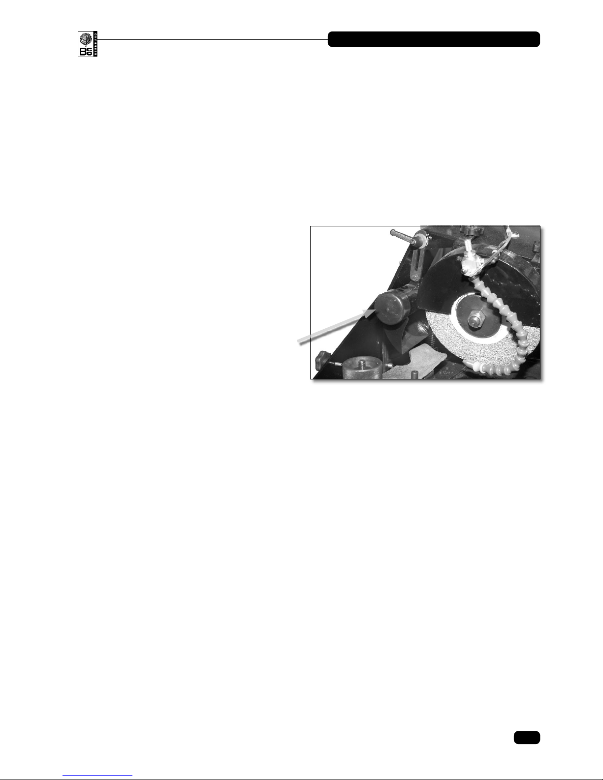
3.2.4 If not yet done, mount the spark/debris scoop on the side of the grind stone guard where
blade grinding is to take place.
The spark/debris scoop is symmetrical and the end bung and vacuum hose are a push t.
These may be removed, the scoop retted to the alternative mounting point, and then the
bung and hose retted.
3. Setting Up (Continued)
Alternate spark/debris mount
Spark/debris
scoop
Mounting for
Spark/debris
scoop

9
ROTA MASTER • RM3000
© Bernhard and Company Limited
3.2.5 Place the front of the blade on the front pillow block, as close to the tip as practical (this
may be determined by the shape of the blade – an overhang can be tolerated).
NOTE: Always grind the worst end (most worn/damaged) of the blade rst.
Slide the upper member of the blade support so that the tapered cone will locate in the
mounting hole of the blade:
Alternatively, place the blade over the threaded pin rst, then locate the blade by
positioning the cone from ABOVE the blade:
3. Setting Up (Continued)

10
ROTA MASTER • RM3000
© Bernhard and Company Limited
3.2.6 The “quick” nut looks as though it has been badly made! Slide it over the central cone pin’
thread. When it rests on top of the blade tighten, as a normal nut, lightly.
CROSS SECTION:
Thread is removed on one side at ‘A’ and ‘B’.
Tilt nut as shown, slide over thread until it rests on
top of blade.
Tighten as a normal nut.
“QUICK NUT”
3.2.7 Position the assembly clamp
over the support assembly, as
close to the cone axis as
possible (better still around it
as shown).
3.2.8 Position the side/anti-rotate
stop over the clamp as shown
(with the large diameter
“emery” friction washer
between) and tighten the lobed
knob to lock the assembly in
position.
3.2.9 Fully tighten the “quick” nut to
lock the blade in position.
NOTE If the blade is located with the cone beneath, the “quick nut” should be tightened with
it’s at face upwards.
If located with the cone from above, lock in place with the at face of the “quick” nut
downwards.
3. Setting Up (Continued)
Indice


