
Rugby LR-26B Istruzioni per l'installazione
03 5804
LR-26B, LR-27B, LR-28A, or LR-623
INSTALLATION AND
OWNER'S MANUAL
To Be Filled In By Installer
Hoist Installed:
Hoist Serial #:
Pump Installation & Operation Manual #:
In-Service Date:
Dealer:
Address:
Dealer Phone#:
Use this manual ONLY if installing or operating an LR-26B, LR-27B, LR-28A, or LR-623 hoist. If
installing or operating a model SF-26B, SF-28A, or SF-623 Sub-frame hoist, refer to manual #03
6077. This manual should be kept in truck glove compartment for reference when needed.
Features LR-26B(03 1440),LR-27B(03 1484),LR-28A(03 1439),LR-623(03 2040)
First Edition: August 1, 1996
Latest Edition: 7 (October 31, 2001)
INDUSTRIAL PARK
515 1ST STREET NORTH EAST
RUGBY, ND 58368
LR-26B, LR-27B, LR-28A, or LR-623
Stock No. 03 5804
Page 2 of 19
IMPORTANT FACTS ABOUT THIS MANUAL
The Rugby®model SF-26B, SF-28A, and SF-623 hoists are installed with a sub-frame. The model
LR-26B, LR-27B, LR-28A, and LR-623 hoists are installed without a sub-frame. If you are install-
ing an LR-26B, LR-27B, LR-28A, and LR-623, this manual (Part #03 5804) is the correct manual.
If you are installing an SF-26B, SF-28A, or SF-623, this manual (part #03 5804) is the incorrect
manual to use. The correct manual (Part #03 6077) should be obtained and used. This manual
(part #03 5804) covers only the installation of the hoist itself and the rear hinge.
This manual does not cover the installation and operation of the body prop or body props. The
installation and operation of the body prop or body props is covered in the manual #03 6034. The
#03 6034 manual is included in every LR-26B, LR-27B, LR-28A, or LR-623 application sold by
Rugby Manufacturing Co.
This manual (part #03 5804) does not cover the installation and operation of the hydraulic system.
There are four different types of hydraulic systems available for some or all of the hoist models
(LR-26B, LR-27B, LR-28A, or LR-623).
The four types of hydraulic systems and their respective installation and operation manuals are listed
below:
Installation and Operation Type of Hydraulic System
Manual Part Number
03 5679 Drive shaft driven pump with mid-latch cable
03 5650 Direct Mount Pump with tower control
03 5669 Electric double acting with push button control
03 5670 Electric single acting with push button control
Depending on the type of hydraulic system purchased, one of the above manuals will be included in
every LR-26B, LR-27B, LR-28A, or LR-623 sold by Rugby Manufacturing Co. Before installing
one of the before mentioned hoists, be sure you have the proper manuals to do the job. If you do not
have the correct manuals contact Rugby Manufacturing Co.

LR-26B, LR-27B, LR-28A, or LR-623
Stock No. 03 5804
Page 3 of 19
"CAUTION"
The hydraulic system supplied with a given hoist manufactured by Rugby Manufacturing Co. is
made up of components (pump, valves, reservoir, hoses, cylinder, etc.) that are designed to be
compatible with each other.
If you substitute hydraulic components, it is your responsibility to BE SURE they are compatible
with the other components supplied by Rugby Manufacturing Co. Incompatible hydraulic
components may cause failure of the hoist which in turn could damage the truck, damage other
property, and cause human injury or death.
All Rugby Manufacturing Co.'s liability and warranty for a given hoist will be voided if it is
determined by Rugby Manufacturing Co. that substituted hydraulic components were used that were
incompatible with those supplied by Rugby Manufacturing Co.
Several hoist hydraulic parameters are given in the following table. These parameters are given as a
general guide. To ensure component compatibility, consult Rugby Manufacturing Co.
LR-27B LR-26B
LR-28A
HOIST MODEL LR-623
"MAXIMUM"
HYDRAULIC 12 GPM 9GPM
FLOW RATE (GPM)
"MAXIMUM"
PRESSURE FOR 2350 PSI 3200 PSI
RAISING PORTION
OF DUMP CYCLE (PSI)
"MAXIMUM"
PRESSURE FOR 750 PSI 1000 PSI
LOWERING PORTION
OF DUMP CYCLE (PSI)

LR-26B, LR-27B, LR-28A, or LR-623
Stock No. 03 5804
Page 4 of 19
The following step-by-step instructions are to be followed as a general guideline when
installing the LR-26B, LR-27B, LR-28A, or LR-623 hoist assembly:
Warning: Welding, oxy-fuel cutting, or grinding sparks can cause fuel to ignite which
in turn can lead to injury or death. "Always" take adequate steps to avoid
ignition of fuel from fuel tanks when welding, grinding, or oxy-fuel cutting
during equipment installation.
Warning: Heat from the truck's exhaust system can cause hydraulic component failure
and may lead to a fire which could cause injury or death. "Always" install
equipment in locations where heat from the exhaust system will not damage
any hydraulic component.
Warning: Being under a raised body can result in serious injury or death should the
body inadvertently descend. "Never" position yourself or allow others to
position themselves under a "loaded" body. "Always" prop the "unloaded"
body up using the body prop or body props supplied. "Remember", body
props are to be used only on an unloaded body.
Warning: Malfunctioning equipment can cause property damage, injury or death.
"Always" have faulty equipment repaired before continuing its use. If
required, consult the manufacturer.
Warning: Overloading of a truck can cause truck component damage, or an accident
which may cause injury or death. "Never" exceed the gross vehicle weight
(GVW) or the gross axle weight (GAW) rating of your vehicle.
Warning: Not installing or operating equipment correctly can cause component
damage, or an accident which may cause injury or death. "Always" install
and operate equipment in accordance with manufacturer's instructions. Read
and understand this manual fully before proceeding.
LR-26B, LR-27B, LR-28A, or LR-623
Stock No. 03 5804
Page 5 of 19
ABOUT RUGBY®HOISTS
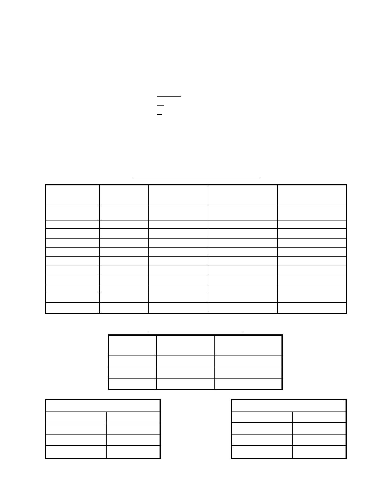
Capacities are based on water level, non-diminishing loads. Because of the variations in truck equip-
ment and cab axles (CA), the data contained in the following data sheets are provided only as a general
guide. The following values for capacities are in accordance with NTEA rating procedures.
LR-26B, LR-27B, LR-28A, or LR-623
Stock No. 03 5804
Page 6 of 19
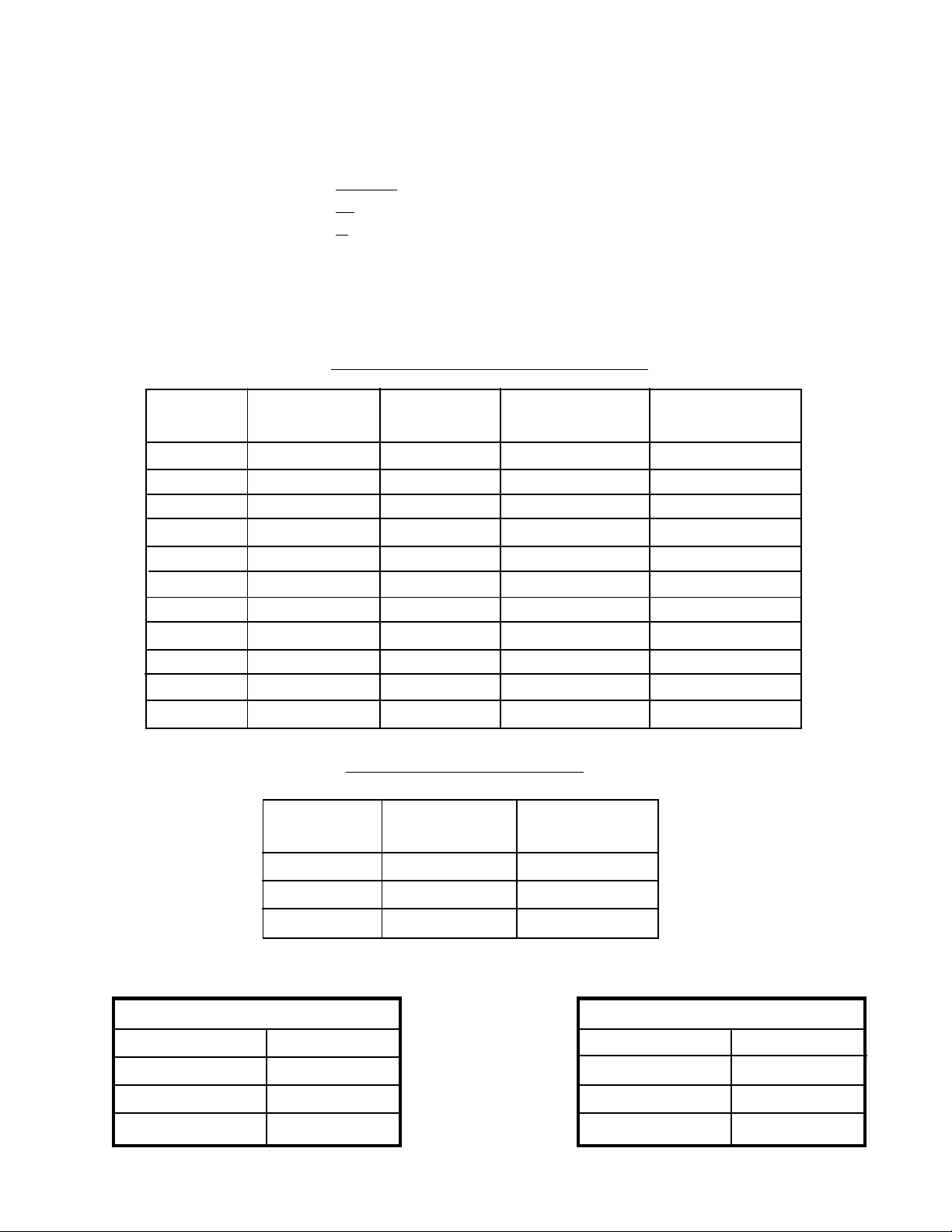
MODEL: LR-26B
DUMP CLASS 50
CONVERSION CLASS: E
6" dia. piston; 20" stroke; 102" to 120" CA; 13' to 16' box; 400to 500dump angle; 7 1/4" mounting
height; 6" long beams recommended.
LR-26B CONVERSION APPLICATION
BODY REAR CAPACITY CAPACITY CAPACITY
LENGTH OVERHANG 400DUMP 450 DUMP 500 DUMP
13' 42" 26 Ton 23 Ton 21 Ton
13' 30" 19 Ton 17 Ton 15 Ton
13' 24" 17 Ton 15 Ton 14 Ton
14' 42" 22 Ton 20 Ton 18 Ton
14' 36" 19 Ton 17 Ton 15 Ton
14' 30" 17 Ton 15 Ton 14 Ton
15' 48" 22 Ton 20 Ton 18 Ton
15' 42" 19 Ton 17 Ton 15 Ton
15' 36" 17 Ton 15 Ton 14 Ton
16' 48" 19 Ton 17 Ton 15 Ton
16' 42" 17 Ton 15 Ton 14 Ton
LR-26B DUMP APPLICATION
BODY
LENGTH OVERHANG
CAPACITY
50oDUMP
10' 12" 15 Ton
11' 12" 14 Ton
12' 12" 12 Ton
REVERSE MOUNTING
DUMP ANGLE M dimension
400109"
45098"
50088"
STANDARD MOUNTING
DUMP ANGLE M dimension
400111"
450100"
50090"
LR-26B, LR-27B, LR-28A, or LR-623
Stock No. 03 5804
Page 7 of 19
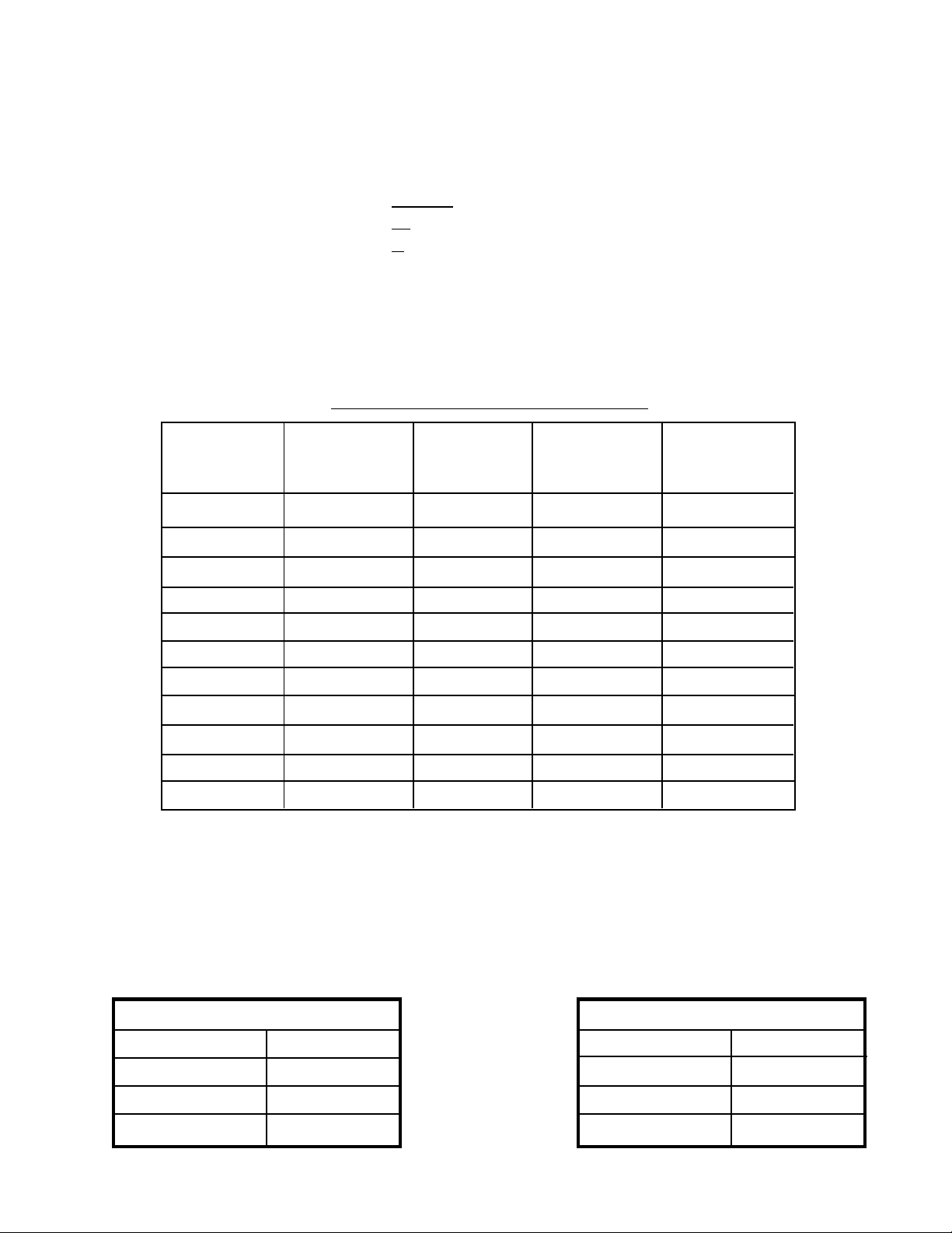
MODEL: LR-27B
DUMP CLASS 50
CONVERSION CLASS E
7" dia. piston; 20" stroke; 102" to 120" CA; 13' to 16' box; 400to 500 dump angle; 7 1/4" mounting
height; 6" long beams recommended.
LR-27B CONVERSION APPLICATION
BODY REAR CAPACITY CAPACITY CAPACITY
LENGTH OVERHANG 400DUMP 450DUMP 500DUMP
13' 42" 26 Ton 23 Ton 21 Ton
13' 30" 19 Ton 17 Ton 15 Ton
13' 24" 17 Ton 15 Ton 14 Ton
14' 42" 22 Ton 20 Ton 18 Ton
14' 36" 19 Ton 17 Ton 15 Ton
14' 30" 17 Ton 15 Ton 14 Ton
15' 48" 22 Ton 20 Ton 18 Ton
15' 42" 19 Ton 17 Ton 15 Ton
15' 36" 17 Ton 15 Ton 14 Ton
16' 48" 19 Ton 17 Ton 15 Ton
16' 42" 17 Ton 15 Ton 14 Ton
LR-27B DUMP APPLICATION
BODY CAPACITY
LENGTH OVERHANG 500 DUMP
10' 12" 15 Ton
11' 12" 14 Ton
12' 12" 12 Ton
REVERSE MOUNTING
DUMP ANGLE M dimension
400109"
45098"
50088"
STANDARD MOUNTING
DUMP ANGLE M dimension
400111"
450100"
50090"
LR-26B, LR-27B, LR-28A, or LR-623
Stock No. 03 5804
Page 8 of 19
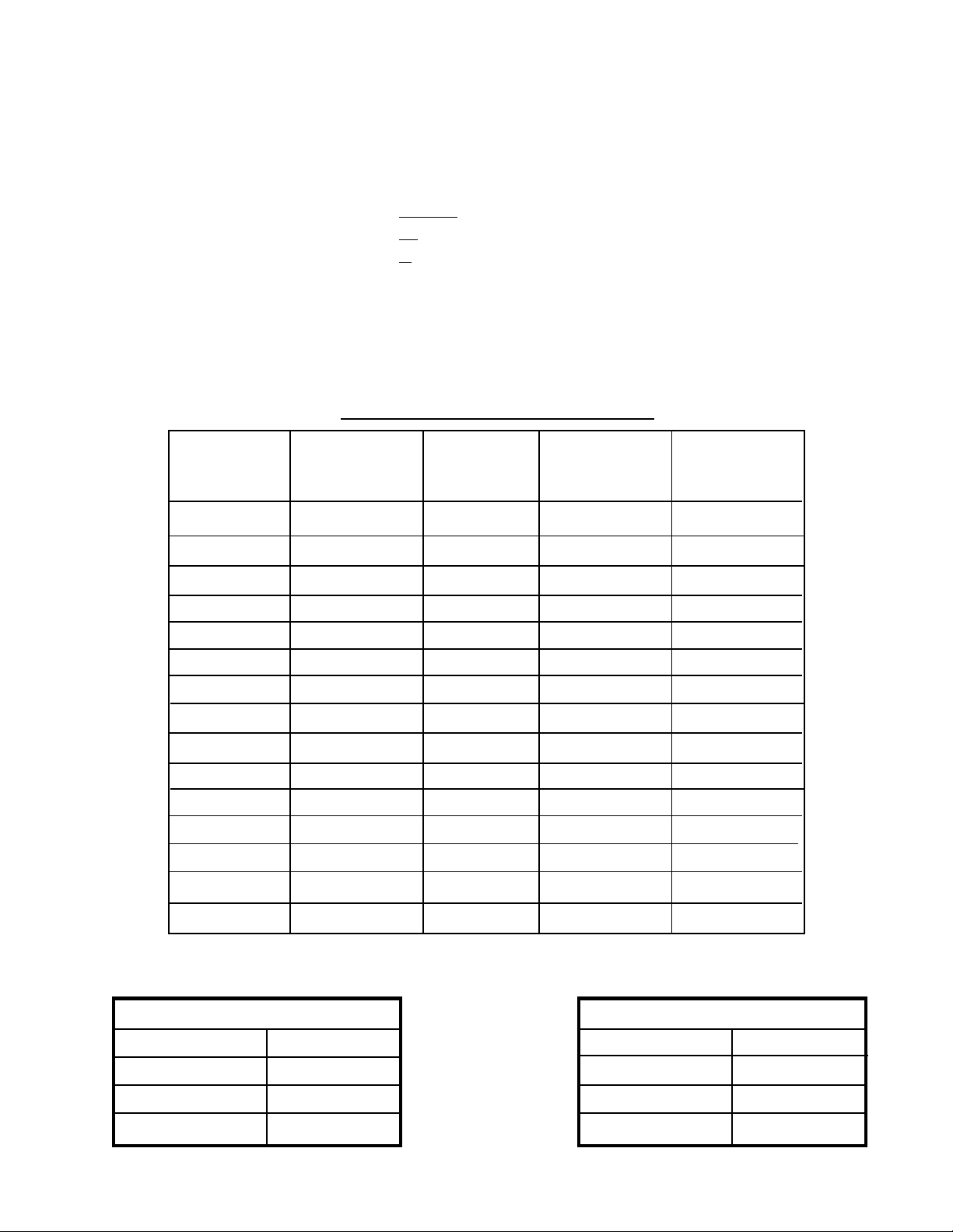
MODEL: LR-28A
DUMP CLASS: 60
CONVERSION CLASS: F
6" dia. piston; 28" stroke; 114" to 138" CA; 16' to 18' box; 400to 500dump angle; 8 1/4" mounting
height; 7" long beams recommended.
LR-28A CONVERSION APPLICATION
BODY REAR CAPACITY CAPACITY CAPACITY
LENGTH OVERHANG 400 Dump 450Dump 500 Dump
13' 12" N/A 16 Ton 15 Ton
14' 24" N/A 18 Ton 16 Ton
15' 36" N/A 20 Ton 18 Ton
15' 30" N/A 18 Ton 16 Ton
16' 42" N/A 20 Ton 18 Ton
16' 36" 20 Ton 18 Ton 16 Ton
17' 48" 22 Ton 20 Ton 18 Ton
17' 42" 20 Ton 18 Ton 16 Ton
17' 36" 18 Ton 16 Ton 15 Ton
18' 42" 18 Ton 16 Ton 15 Ton
18' 48" 20 Ton 18 Ton 16 Ton
REVERSE MOUNTING
DUMP ANGLE M dimension
400144"
450129"
500118"
STANDARD MOUNTING
DUMP ANGLE M dimension
400146"
450131"
500120"
LR-26B, LR-27B, LR-28A, or LR-623
Stock No. 03 5804
Page 9 of 19
MODEL: LR-623
DUMP CLASS: 50
CONVERSION CLASS: F
6" dia. piston; 23" stroke; 10' to 18' box; 400to 500dump angle; 8" mounting height; 7" long beams
recommended.
LR-623 CONVERSION APPLICATION
BODY REAR CAPACITY CAPACITY CAPACITY
LENGTH OVERHANG 400 Dump 450Dump 500 Dump
10' 6" N/A 19 Ton 18Ton
11' 18" N/A 22 Ton 20 Ton
12' 6" 18 Ton 16 Ton 14 Ton
13' 18" 20 Ton 17 Ton 16 Ton
13' 24" 22 Ton 19 Ton 18 Ton
13' 42" N/A 29 Ton 27 Ton
14' 18" 18 Ton 16 Ton 14 Ton
14' 30" 22 Ton 19 Ton 18 Ton
14' 36" 25 Ton 22 Ton 20 Ton
16' 18" 15 Ton 13 Ton 12 Ton
16' 24" 16 Ton 14 Ton 13 Ton
16' 42" 22 Ton 19 Ton 18 Ton
18' 18" 13 Ton 11 Ton 10 Ton
18' 30" 15 Ton 13 Ton 12 Ton
18' 42" 18 Ton 16 Ton 14 Ton
REVERSE MOUNTING
DUMP ANGLE M dimension
400117.75"
450105.25"
50095.25"
STANDARD MOUNTING
DUMP ANGLE M dimension
400119.0"
450106.5"
50096.5"
LR-26B, LR-27B, LR-28A, or LR-623
Stock No. 03 5804
Page 10 of 19
LR-26B, LR-27B, LR-28A, & LR-623 ASSEMBLY INSTRUCTIONS
NOTE: If you are installing a SF-26B, SF-28A, or SF-623 refer to manual with
Part #03 6077.
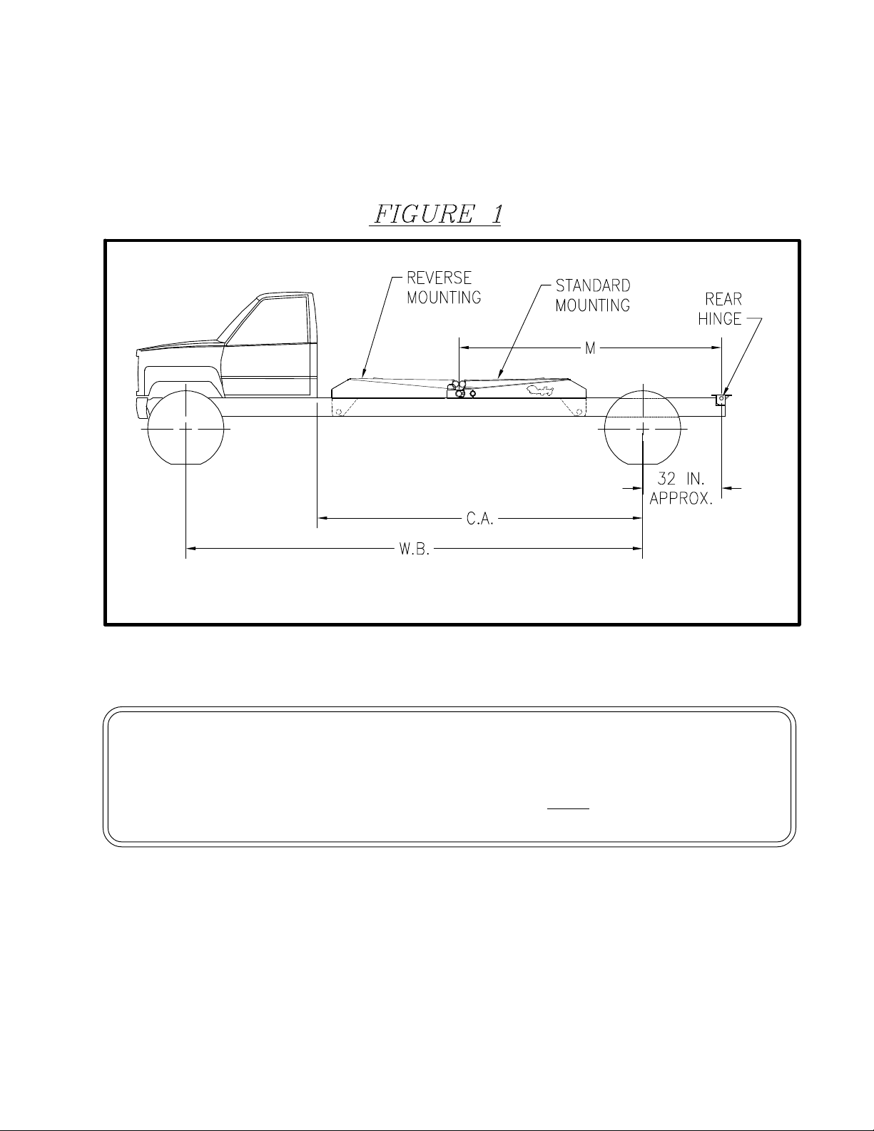
1. Mark the location for the rear hinge. This location should be immediately behind a truck
cross member, approximately 32" behind the center of the rear axle on single axle trucks.
Refer to Fig. #1 and the charts for the specific hoist model you are installing.
NOTE: If a distance of 38" is exceeded between the rear hinge and the center of the rear axle,
additional reinforcement of the truck frame will be required.
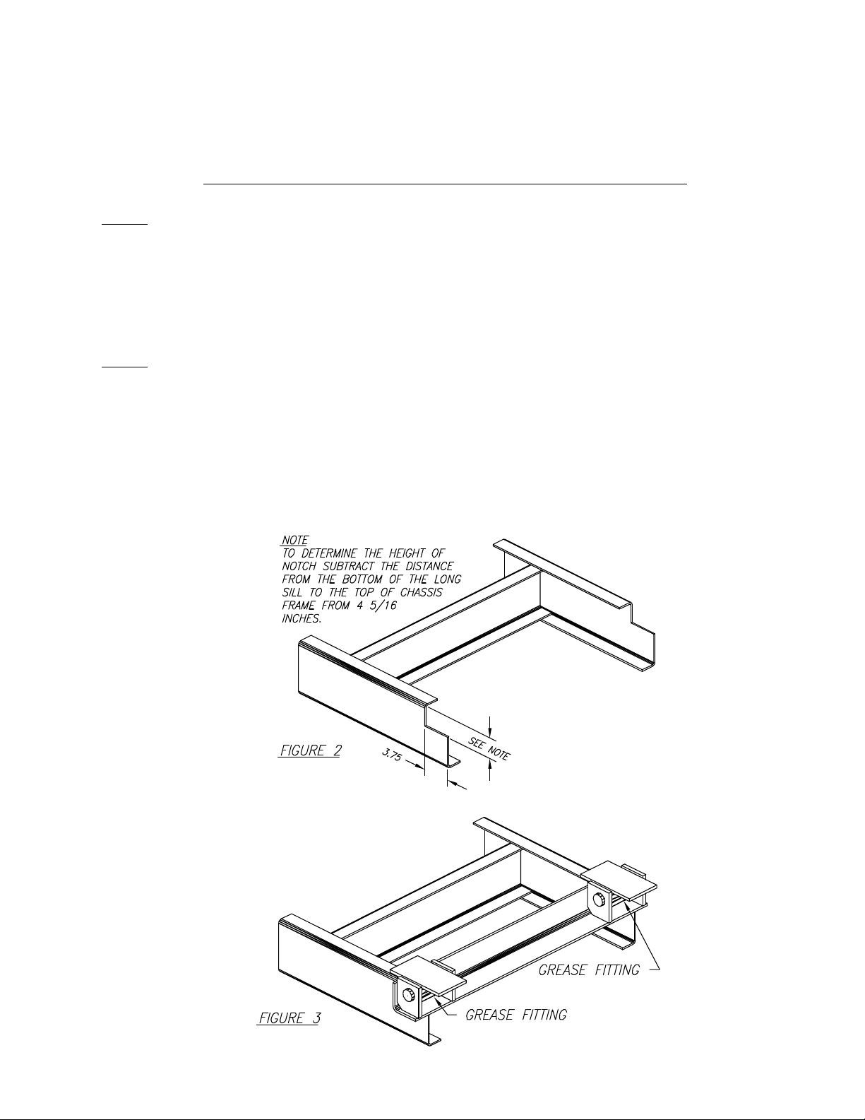
2. Cut a notch in each truck chassis frame rail as illustrated in Fig. #2.
3. Position the rear hinge angle in the notch cut in Step 2. The rear hinge angle is 38 1/16" wide
and should be centered side to side in the notch as illustrated in Fig. #3. Weld the rear hinge
angle to each of the truck chassis frame rails.
Questo manuale è adatto per i seguenti modelli
3
Altri manuali Rugby Accessori per automobili


