
Safesight SC9003 Istruzioni per il montaggio
SAFESIGHT
™
SC9003
Reverse back up camera system
Installation Guide and
User’s Manual
Version 1

Table of Contents
1. Introduction...................................................................................................................................................................................................1
1.1 Notes and Warnings .......................................................................................................................................................................1
2. Installation/Setup .......................................................................................................................................................................................2
2.1 LCD monitor shroud removal.....................................................................................................................................................2
2.2 Method 1 – Shroud removal using a scre driver .............................................................................................................3
2.3 Method 2 – Shroud removal using a credit card ................................................................................................................4
2.4 Method 2 – Shroud Mounting tabs and receiver................................................................................................................5
3. Monitor Wiring harness ...........................................................................................................................................................................6
3.1 Identifying the bare ires............................................................................................................................................................6
3.2 Method Identifying the RCA cables..........................................................................................................................................7
3.3 Monitor cable diagram ..................................................................................................................................................................8
3.4 Multi-pin connector connection ................................................................................................................................................9
4. Back up camera .........................................................................................................................................................................................10
4.1 Identifying the camera connections .....................................................................................................................................10
4.2 Back up camera cable diagram ...............................................................................................................................................11
5. Camera extension cable.........................................................................................................................................................................12
5.1 Identifying the camera extension cable connections....................................................................................................12
5.2 Back up Camera Cable Diagram..............................................................................................................................................13
6. System connections..........................................................................................................................................................................14-15
6.1 Cable connections ..................................................................................................................................................................14-15
6.2 System Diagram.............................................................................................................................................................................16
6.3 In-line fuse connection ...............................................................................................................................................................17
6.4 Main po er connection.......................................................................................................................................................18-19
6.5 Reverse trigger connection ...............................................................................................................................................20-21
7. Troubleshooting........................................................................................................................................................................................22
7.1 Unit ill not turn on hen the vehicle is placed in reverse.......................................................................................23
7.2 Monitor turns on but camera does not hen placed in reverse..............................................................................22
7.3 Monitor and camera ill not turn on after the vehicle is taken out of reverse.................................................23
7.4 Monitor randomly turns on and off. .....................................................................................................................................23

Safesight SC9003 Back up camera system .qualitymobilevideo.com
Page 1
1. Introduction
Thank you for purchasing the Safesight SC9003 Reverse camera system! This system ill
help prevent the most deadly type of automobile accidents, reversing accidents. All that’s
left is to install and use your system. In the follo ing information e ill guide you
through installing your system and getting the most out of it.
First e begin ith a couple of things you should have on hand to help ith the installation
of your system:
•Voltmeter or DMM
•Basic hand tools, i.e. (pliers, scre driver, socket set)
•Electrical tape
•Wire ties
•Crimp connectors
•Wire crimper
1.1 Notes and Warnings
Here e sho you ho e ill outline different things that ill help and point things out
during the course of your installation and use. (as sho n belo ).
Note: Notes ill be highlighted in this yello box.
Warning: Warnings ill be highlighted in this orange box.

Safesight SC9003 Back up camera system .qualitymobilevideo.com
Page 2
2. Installation/Setup
We begin by identifying the contents of the back up camera system:
1. LCD Monitor
2. Back up camera
3. Monitor iring harness
4. Camera iring harness
5. Extension cable
6. Remote Control
7. Mounting stand
8. Headrest shroud
Warning: All electrical connections should be done after removing the negative post
of the battery. Under no circumstance does qualitymobilevideo.com assume any
liability. Use these instructions at your own risk. These instructions are meant as a
guide but require knowledge by the installer. f you are unfamiliar please seek
professional advice prior to any and all installation.
2.1 LCD monitor shroud removal
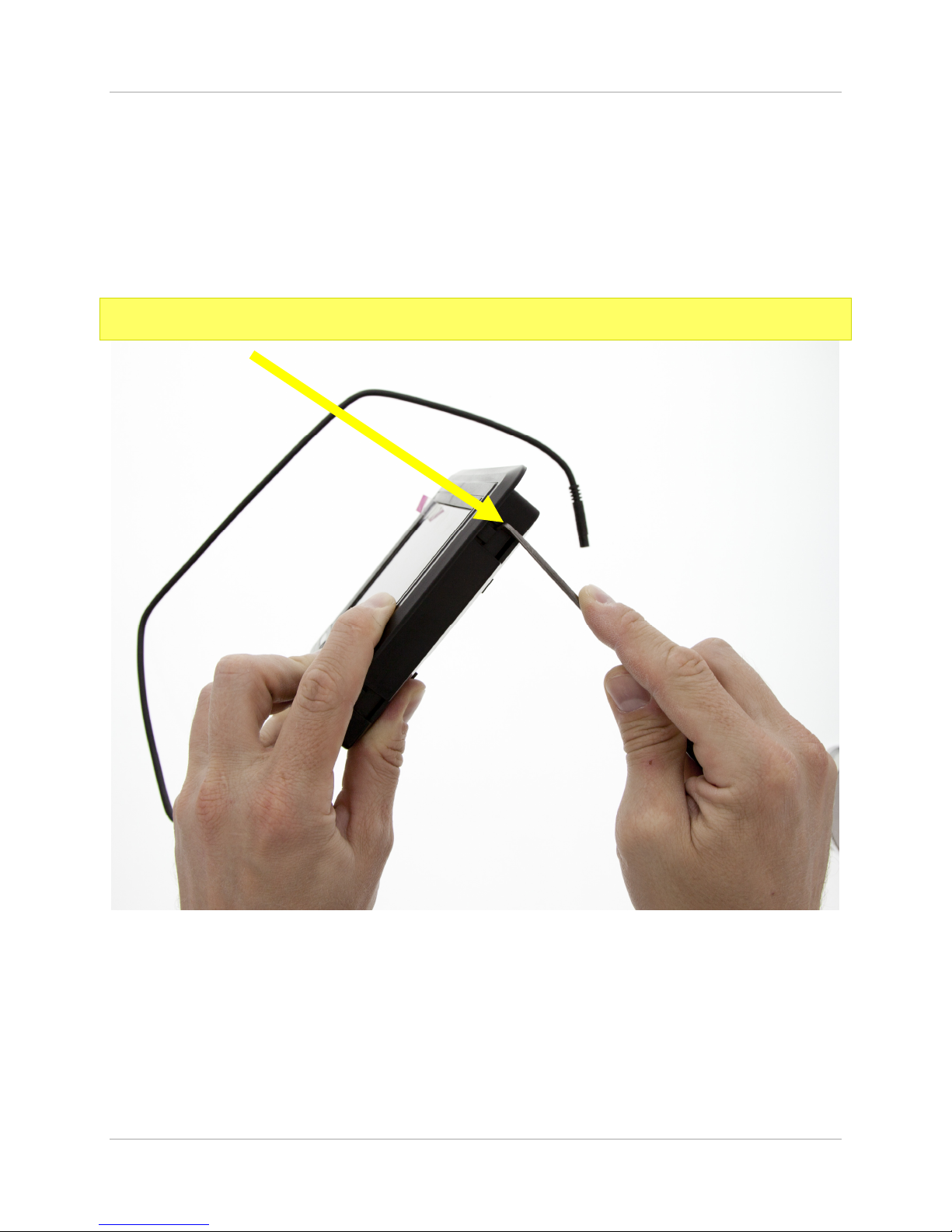
When un-packaging the monitor you ill typically find the monitor already inserted into
the headrest shroud. Here is ho to remove the monitor from its shroud. The monitor is
held into the shroud ith t o tabs on the left and right side of the monitor and shroud.
To remove the monitor from the shroud you ill need to carefully pry the tab ith a small
flat head scre driver or pick.
Warning: these tabs can break very easily if pried too far.
Safesight SC9003 Back up camera system .qualitymobilevideo.com
Page 3
2.2 Method 1: - Shroud removal using a screwdriver
See the picture belo for added clarification on the removal of the monitor from its shroud.
Note: Carefully insert the screwdriver or pick and gently pry the tab back.
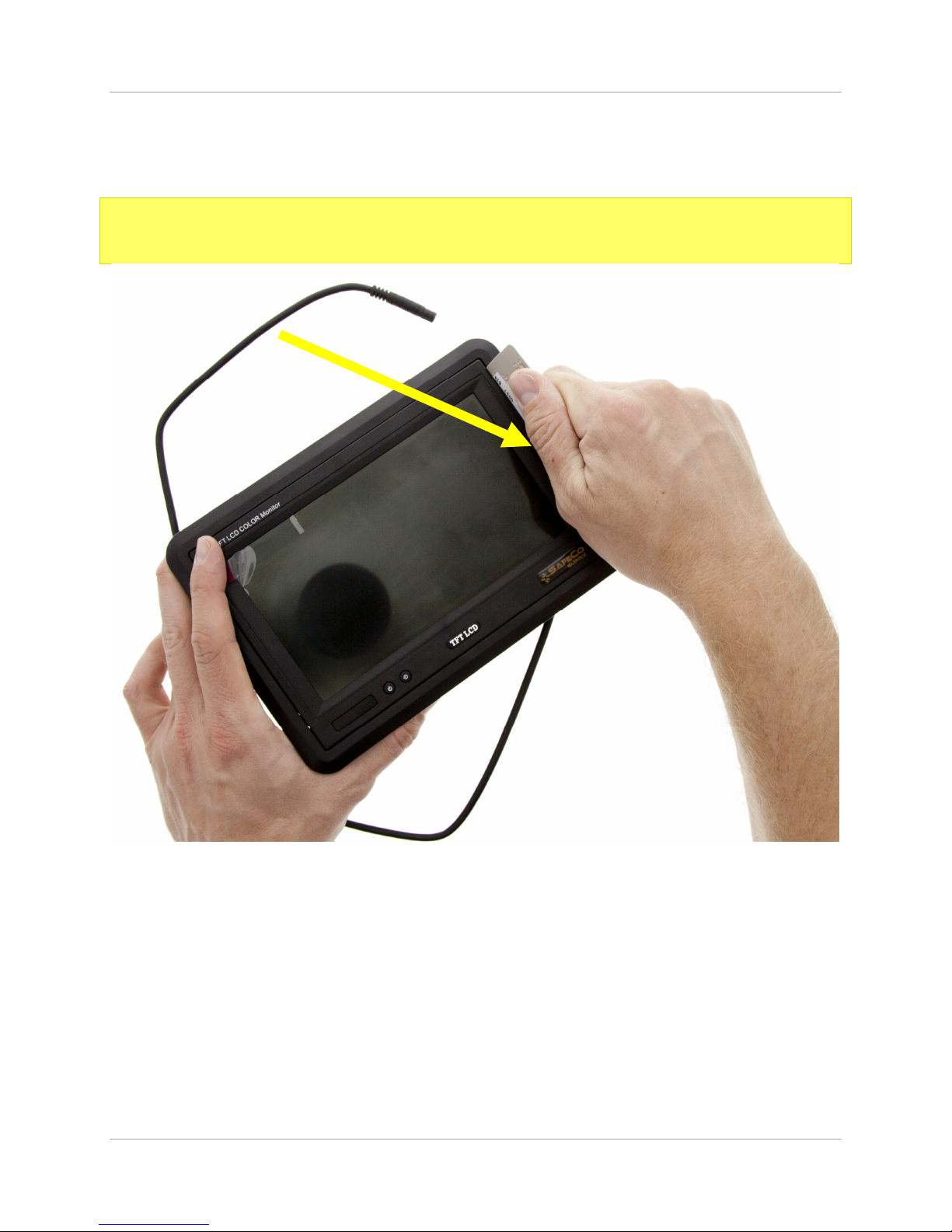
If the shroud is installed and you cannot access the tabs or you fear breaking the tab there
is another method to remove the monitor from its shroud. See method 2 on the next page.
Safesight SC9003 Back up camera system .qualitymobilevideo.com
Page 4
2.3 Method 2: - Shroud removal using a credit card
Note: Carefully insert a credit card in between the monitor housing and the shroud
gap
Safesight SC9003 Back up camera system .qualitymobilevideo.com
Page 5
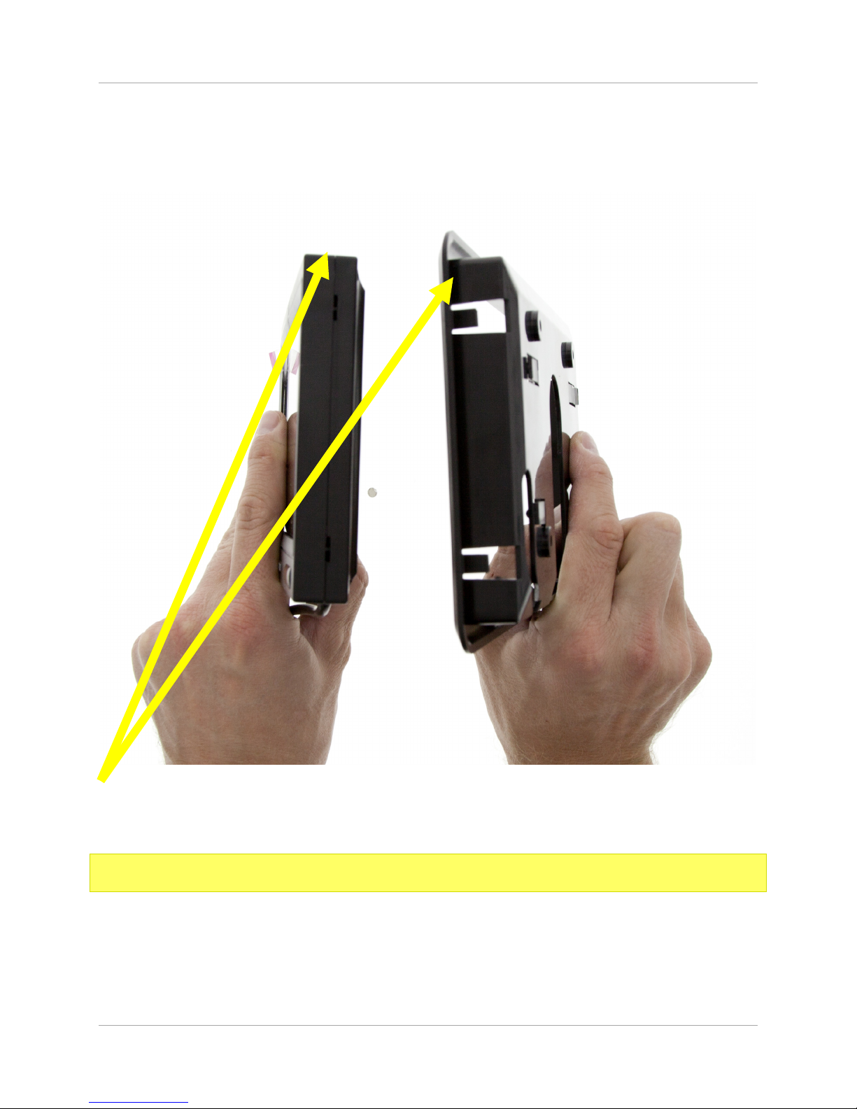
2.4 Shroud mounting tabs and
receivers
Note: The rectangular slot and tab lock into one another

Safesight SC9003 Back up camera system .qualitymobilevideo.com
Page 6
3. Monitor wiring harness
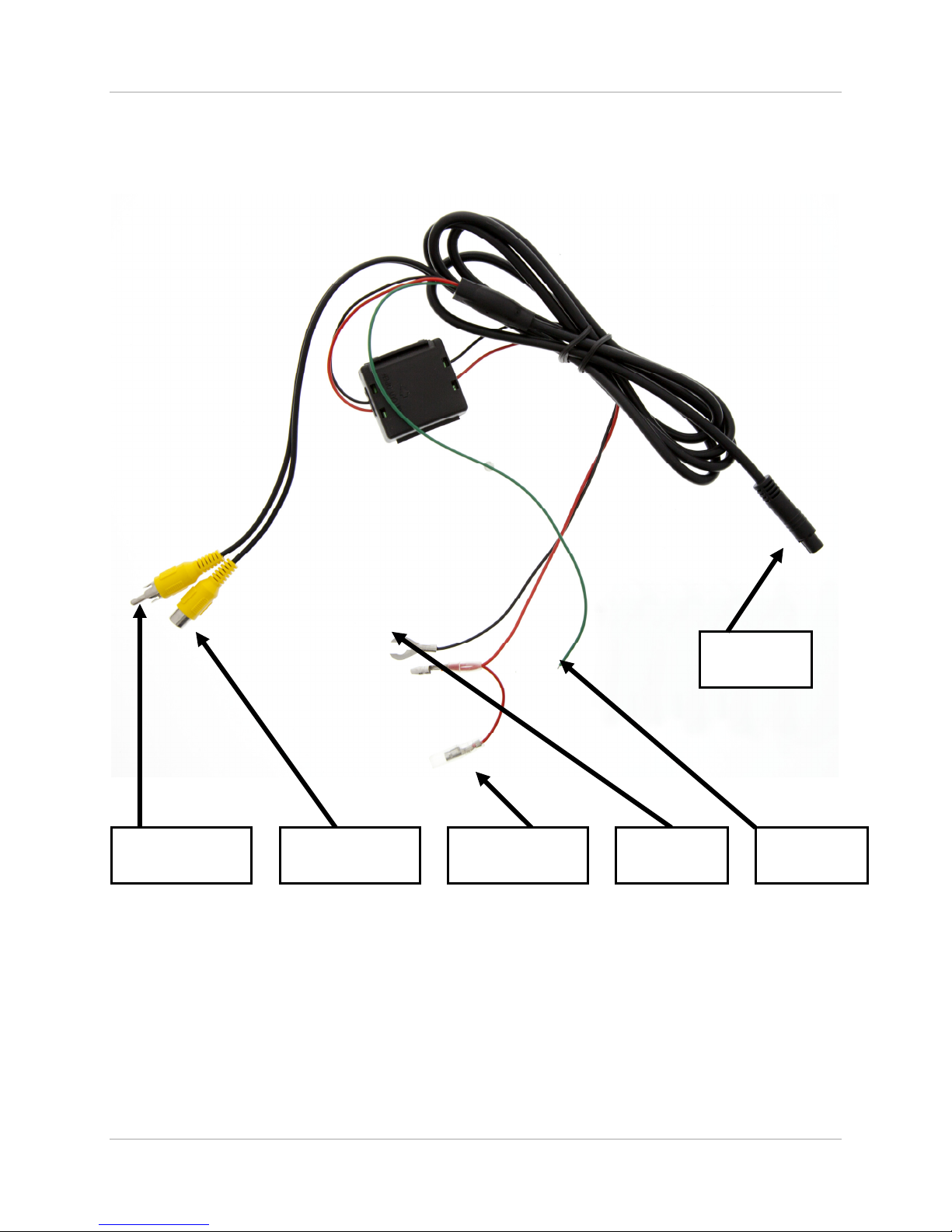
The monitor iring harness is a single harness that has a multi-pin connector on one end
and a series of ires and RCA cables on the other. The black box contains a po er filter and
fuse that prevents damage in the event of a short circuit. The multi-pin connector has a tab
that prevents the connectors from being inserted incorrectly to one another.
Note: n the event that the monitor will not respond please check to make sure the
fuse is seated properly and fuse is not blown.
3.1 Identifying the bare wires
Bare Wire color Connection
Red
Positive + 12 volts – connect this to a
switched power supply at the fuse box so
that the monitor will get power only when
the key is on.
Black Negative – 12 volts – connect this to the
ground of the vehicle.
Green
Positive + 12 volt trigger – when 12 volts is
applied to this wire it will trigger the
monitor to turn on to the camera input, this
will prevent you from turning the monitor
off until 12 volts is removed from this wire.

Safesight SC9003 Back up camera system .qualitymobilevideo.com
Page 7
3.2 Identifying the RCA cables
RCA Cable Connection
Male RCA Cable
Connect this to a secondary camera or
DVD source. This input is not trigger-able
and can only be used if 12 volts is not
applied to the green trigger wire.
Female RCA Cable
Connect this to the back up camera or to a
source that you want to display when 12
volts is applied to the green trigger wire.
Safesight SC9003 Back up camera system .qualitymobilevideo.com
Page 8
3.3 Monitor cable diagram
Male RCA
Cable
Female RCA
Cable
Red bare ire
Black bare
ire
Green
bare ire
Multi-pin
connector
Indice


