3 Connections
3.1 Electrical connections
For electrical installation, you are re-
quired to observe the relevant
electrotechnical regulations and the
accident prevention regulations that
apply in the country of use. In Ger-
many, these are the VDE regulations
and the accident prevention regula-
tions of the employers' liability insur-
ance association.
The following standards apply for in-
stallation in hazardous areas:
EN 60079-14: 2003 (VDE 0165
Part 1) "Electrical apparatus for ex-
plosive gas atmospheres" and
EN 50281-1-2: 1999 (VDE 0165
Part 2) "Electrical apparatus for use
in the presence of combustible dust".
For the interconnection of intrinsically
safe electrical equipment, the permis-
sible maximum values specified in the
EC type examination certificate apply
(Uior U0; Iior I0; Pior P0; Cior C0,
and Lior L0).
Note for Zone 2 and Zone 22 equip-
ment :
For EEx nA equipment (non-sparking
apparatus), the standard EN 50021:
1999 specifies that connecting, inter-
rupting, or switching circuits while en-
ergized is only allowed during instal-
lation, maintenance or repair work.
For EEx nL equipment (energy-limited
apparatus), the standard EN 50021:
1999 allows this type of equipment to
be switched under normal operating
conditions.
Caution!
The terminal assignment specified in the cer-
tificate must be adhered to. Reversing the
assignment of the electrical terminals may
cause the explosion protection to become in-
effective!
Do not tamper with enameled screws inside
or on the housing.
Note on the selection of cables and wires:
To install intrinsically safe circuits, observe
section 12 of the standard EN 60079-14:
2003 (VDE 0165 Part 1). To run multi-core
cables or lines with more than one intrinsi-
cally safe circuit, section 12.2.2.7 of this
standard applies.
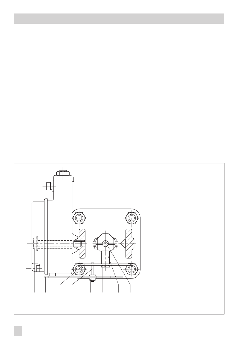
An additional cable gland can be installed
when connecting the device over two sepa-
rate cables. Cable entries left unused must
be sealed with blanking plugs. Devices used
at ambient temperatures down to –40 °C
must have metal cable entries.
10 EB 8359-2 EN
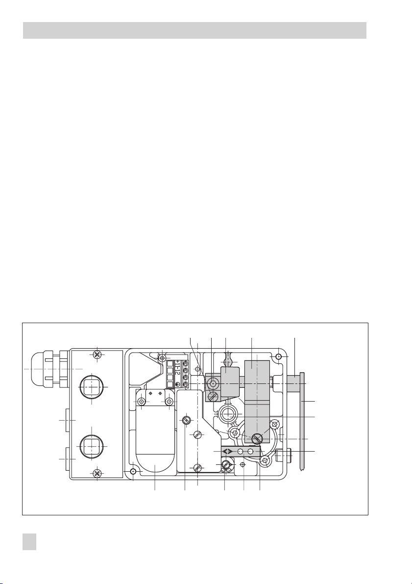
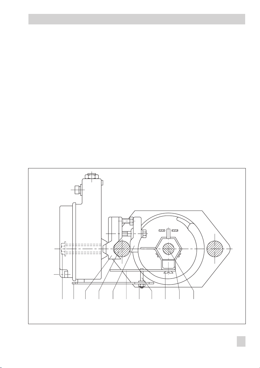
Connections
Fig. 6 · Electrical connection
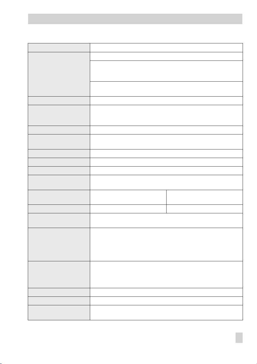
Input
Control signal
4 (0) to 20 mA