schmalenberger fluvo Manuale utente
Air Button
Operator’s Manual
27121 - B
GB
Translation of the original

TABLE OF CONTENTS
2 Air button
Version: 27121 - B
Schmalenberger GmbH + Co. KG
D-72072 Tübingen / Germany
Table of Contents
1 General information.......................................................................... 3
1.1 User information.............................................................................................................. 3
1.2 Other applicable documents........................................................................................... 3
1.3 Safety instructions........................................................................................................... 3
1.4 Proper use ...................................................................................................................... 4
1.5 Responsibilities of the operator....................................................................................... 4
1.6 Signs and symbols.......................................................................................................... 4
1.7 Disposal ......................................................................................................................... 5
2 Description of the device / technical data ...................................... 5
2.1 Description of the device................................................................................................. 5
2.2 Technical data ............................................................................................................... 5
3 Preparation for installation and assembly...................................... 5
3.1 Installation process - general information ..................................................................... 5
3.2 Installation process for concrete tile pools and/or pools with brush-applied sealant 6
3.3 Installation process for concrete liner pool ............................................................... 7
3.4 Extension (for compensation >25 mm) .......................................................................... 8
3.5 Installation process for pre-fabricated pool (installation kit) .......................................... 9
3.6 Installation process for pre-fabricated pool (assembly kit) .......................................... 10
3.7 Installation process - subsequent installation .............................................................. 11

OPERATING INSTRUCTIONS
3
Air button
Version: 27121-B Schmalenberger GmbH + Co. KG
D-72072 Tübingen / Germany
1 General information
1.1 User information
This Operator's Manual makes it easier to become familiar with the device and make full
use of its range of options.
It contains important information for operating the device, properly and economically.
Observing the instructions helps to avoid dangers, avoid repair costs and downtimes,
increase reliability and extend the service life of the device.
The device is built according to the state of the art and recognised technical rules.
Nevertheless, danger to life and limb of the operator or third parties, or damage to other
property may arise during use.
1.2 Other applicable documents
Each centrifugal pump has various documents which belong together with the Technical
Documentation for the device. They are:
• Operator's Manual for the device
• The Operator's Manual for the drive
• The Operator's Manual for the accessories listed in the specification
• Acceptance reports from TÜV, etc.
• Performance run report
• Assembly drawing (dimension sheet)
• Specification with all information
Not all the documents named above exist or are included in every case. Observe the
information in the specification in this regard.
1.3 Safety instructions
•Make certain before commissioning that the operating personnel have read and
understood the Operator's Manual.It is the owner rather than the operator who is
responsible for safety!
• The safety requirements and laws for the use of the device which apply to the operating
company and/or country in which it is operated must be observed.
• Use the device only when it is in flawless condition technically and according to its
intended purpose. Be conscious of safety and dangers and observe all the instructions
in this Operator’s Manual!
• Eliminate all malfunctions that could have a detrimental effect on safety immediately.
• Notices placed directly on the centrifugal pump, such as the arrow for direction of
rotation and identification of fluid connections, must always be observed and must be
maintained in legible condition.
• The installation, operating, maintenance, and upkeep instructions in these Operating
Instructions must be observed.
OPERATING INSTRUCTIONS
4 Air button
Version: 27121-B
Schmalenberger GmbH + Co. KG
D-72072 Tübingen / Germany
1.4 Proper use
The device is designed exclusively for installation into a complete machine or system in
accordance with the original specification. Only values defined in the Technical
Documentation or any other data assigned in the specification may be used for operation.
Any other or more extensive use is considered improper use. The manufacturer shall not
be liable for any resulting damage.
The manufacturer must always be consulted regarding adjustments for a new intended
use.
1.5 Responsibilities of the operator
• The owner/operator must therefore take care to ensure
-that the Operator’s Manual is always available for operating personnel
-That the safety instructions in this Operator's Manual are observed
• The operator must ensure that components are properly integrated and that the entire
system has been approved in accordance with the Machinery Directive (98/37 EC).
1.6 Signs and symbols
The following notices are used in the Operator's Manual. They help you to recognize
danger better.
Symbol Meaning:
Warning! Danger of death!
This symbol warns you of dangers due to electrical current.
Caution! Risk of injury! / Risk of damage!
This symbol warns you of dangers due to mechanical effects.
Important:
This symbol warns you of actions that may damage or destroy the device.
Note:
This symbol refers you to information about financially efficient use of the
device.
Environment:
This symbol refers you to information about working and disposing of waste in
an environmentally responsible manner.
OPERATING INSTRUCTIONS
5
Air button
Version: 27121-B Schmalenberger GmbH + Co. KG
D-72072 Tübingen / Germany
1.7 Disposal
2 Description of the device / technical data
2.1 Description of the device
The air button is designed for wall installation in public and private swimming pools. It is
used to turn an electrical device on and off without using an electrical component inside
the swimming pool. The switching pulse is initiated by a wave of pressure (when the switch
is activated).
2.2 Technical data
3 Preparation for installation and assembly
3.1 Installation process - general information
Device:
Dispose of the device in accordance with local requirements for disposal of
industrial waste.
Material for installation kit: ABS / titanium
Preassembled unit material: ABS / titanium
Dimensions of installation kit
(brush-applied sealant flange): Depth 51 mm (256 mm) - (200x200x6 mm)
Dimensions of assembly kit: Ø 110 mm x 23 mm
Standard length (air hose) 5 m
The distance from the air button to the control box should not exceed 25 m.
As the length of the air line or air hose increases, the response time of the
switching signal also increases.
OPERATING INSTRUCTIONS
6 Air button
Version: 27121-B
Schmalenberger GmbH + Co. KG
D-72072 Tübingen / Germany
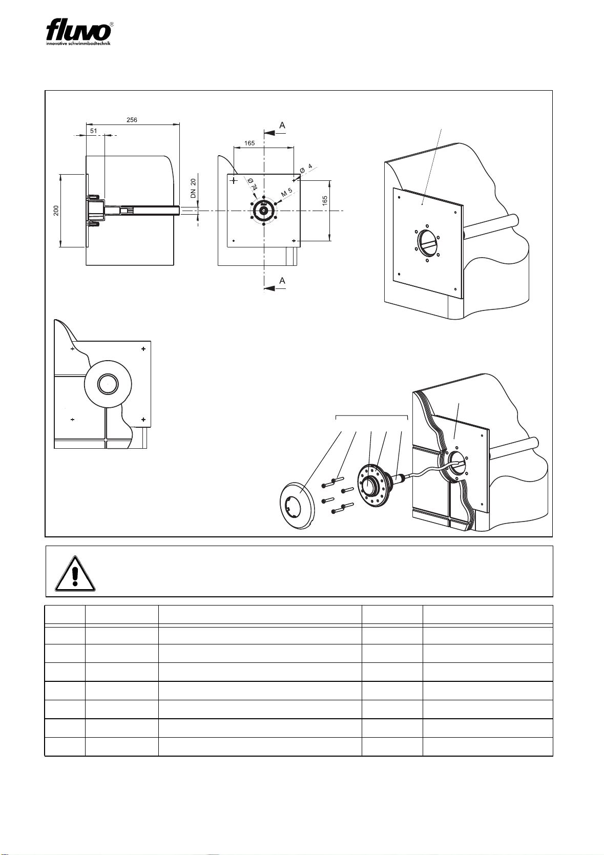
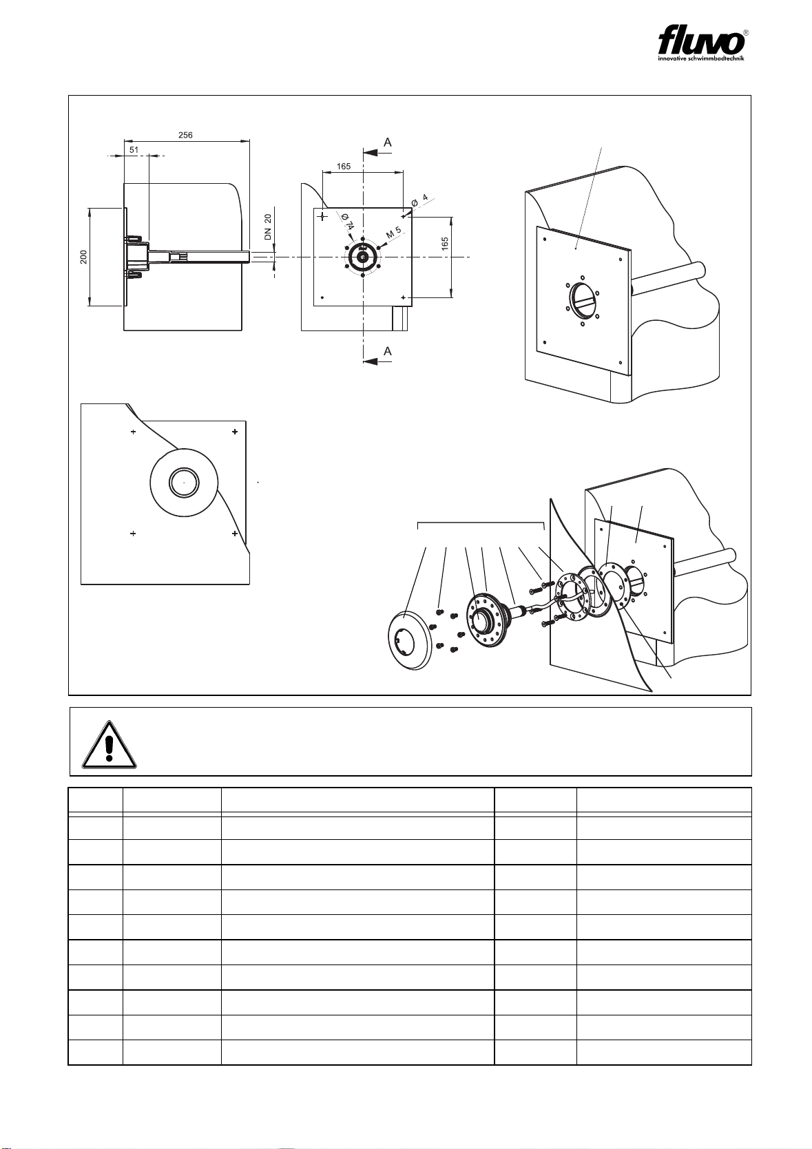
3.2 Installation process for concrete tile pools and/or pools with brush-
applied sealant
Assembly kit - complete with screws (M5) in 3.7035
Maximum compensation 25 mm - beyond this dimension an extension is
required.
Item Order No. Name Pieces Comment
1 60500 Screen 1
2 11033 Cylinder screw 6 M5x50 DIN 7984-3.7035
3 60501 Control button 1
4 60502 Housing 1
5 60507 Insert set - BHS 1 incl. O-rings
6 94700 Installation kit - BHS 1
18 94600 Assembly kit - BS 1
Installation kit - BHS (PVC pipe per DN20)
Fastening onto the mould: nails
Installation kit
Assembly kit
Fig. 1
1 2 3 4 5
6
18
OPERATING INSTRUCTIONS
7
Air button
Version: 27121-B Schmalenberger GmbH + Co. KG
D-72072 Tübingen / Germany
3.3 Installation process for concrete liner pool
Assembly kit - complete with screws (M5) and clamp gasket in 3.7035
Maximum compensation 25 mm - beyond this dimension an extension is
required.
Item Order No. Name Pieces Comment
1 60500 Screen 1
14 11034 Cylinder screw 6 M5x8 DIN 7984-3.7035
3 60501 Control button 1
4 60502 Housing 1
5 60507 Insert set - BHS 1 incl. O-rings
6 94700 Installation kit - BHS 1
8 60506 Clamp gasket 1 PVC soft
9 60515 Clamp gasket 1
10 11072 Counter-sunk screw 6 M5x25 DIN 965-3.7035
19 94602 Assembly kit - H 1
Installation kit - BHS (PVC pipe per DN20)
Fastening onto the mould: nails
Installation kit
Assembly kit
Fig. 2
1 14 3 4 5 10 9
86
19
OPERATING INSTRUCTIONS
8 Air button
Version: 27121-B
Schmalenberger GmbH + Co. KG
D-72072 Tübingen / Germany
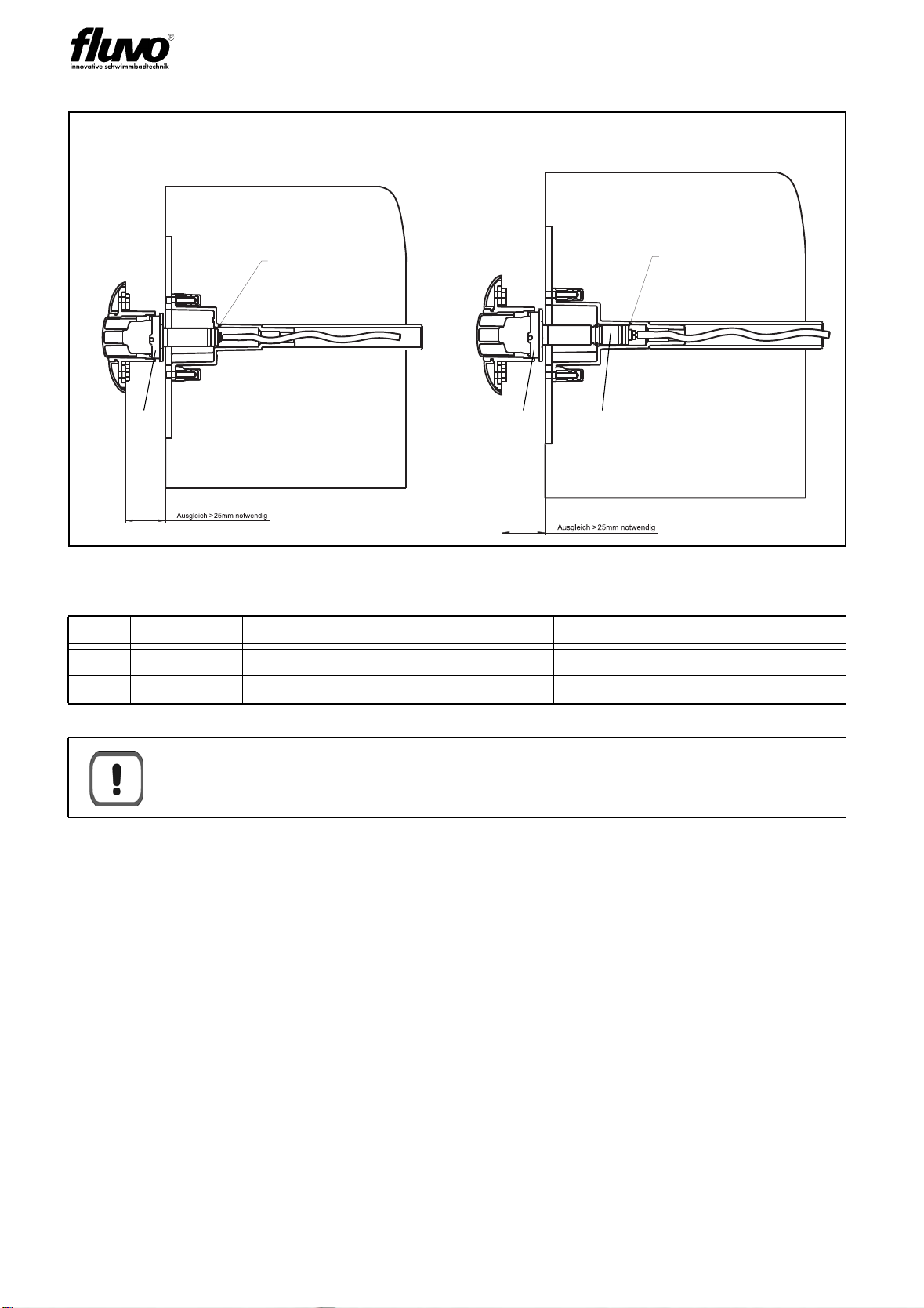
3.4 Extension (for compensation >25 mm)
Fig. 3:
Item Order No. Name Pieces Comment
5 60507 Insert set - BHS 1 incl. O-rings
15 60505 Extension 1 25 mm long
Important:
When gluing the two parts together (installation kit item 5 and extension item
15) make certain that the air aperture remains open!
Assembly kit sealing
in installation kit
no longer ensured Assembly kit sealing
in installation kit ensured
Connection principle - without extension Connection principle - with extension
5155
OPERATING INSTRUCTIONS
9
Air button
Version: 27121-B Schmalenberger GmbH + Co. KG
D-72072 Tübingen / Germany
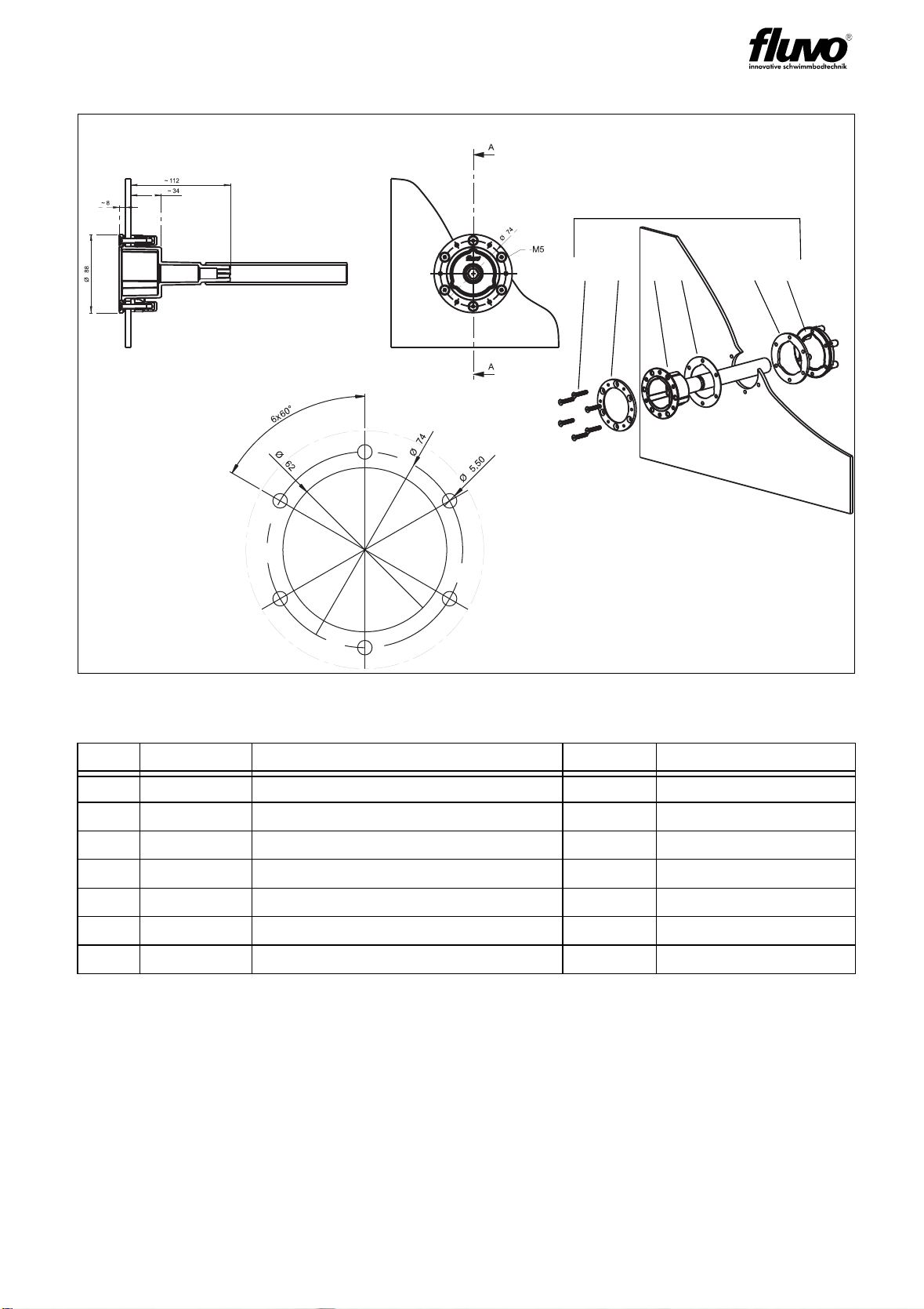
3.5 Installation process for pre-fabricated pool (installation kit)
Fig. 4:
Item Order No. Name Pieces Comment
7 94701 Installation kit - A 1
9 60515 Clamp gasket 1
10 11072 Counter-sunk screw 6 M5x25 DIN 965-3.7035
11 60519 Installation housing - A 1
12 60516 Clamp gasket 1 EPDM
13 60517 Clamp gasket 1 EPDM foam
14 60509 Hold-ring 1 M5-3.7035
Installation kit
Template
10 9 11 12 13 14
7
OPERATING INSTRUCTIONS
1 0 Air button
Version: 27121-B
Schmalenberger GmbH + Co. KG
D-72072 Tübingen / Germany
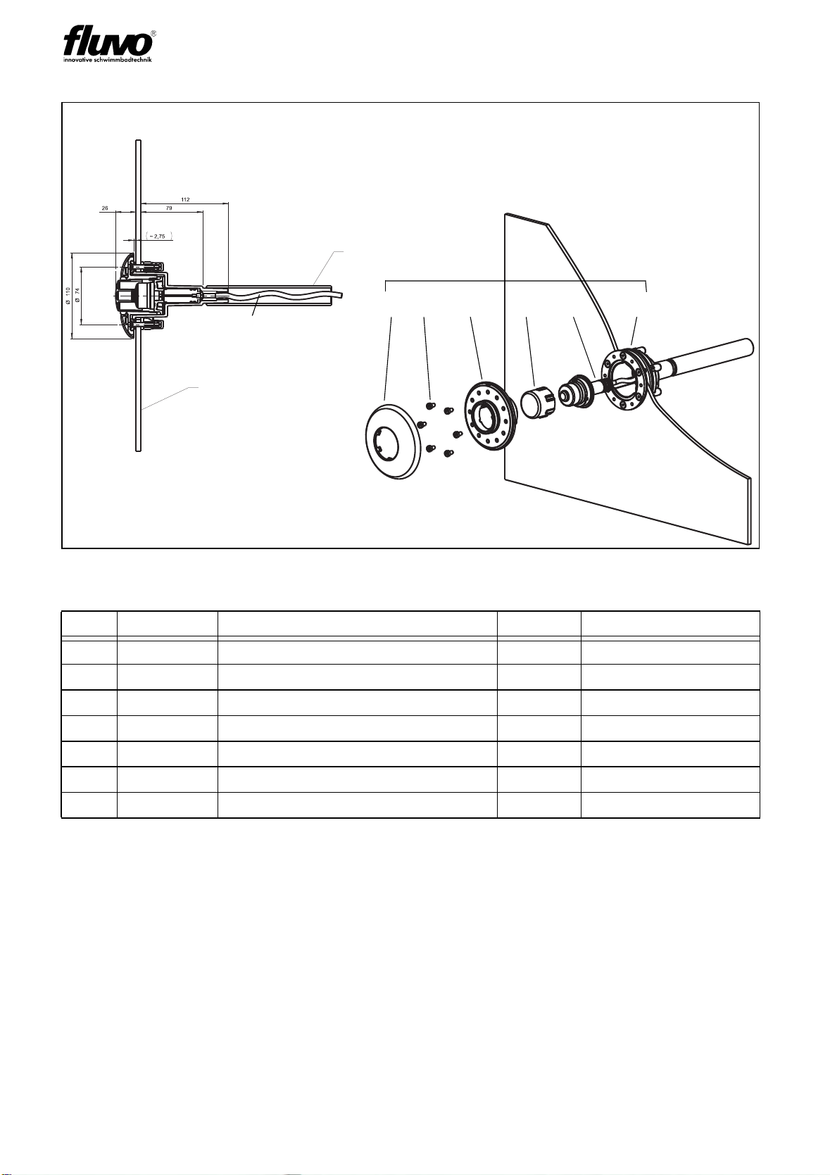
3.6 Installation process for pre-fabricated pool (assembly kit)
Fig. 5:
Item Order No. Name Pieces Comment
1 60500 Screen 1
3 60501 Control button 1
4 60502 Housing 1
7 94701 Installation kit - A 1
14 11034 Cylinder screw 6 M5x8 DIN 7984-3.7035
16 60518 Insert set - A 1 incl. O-rings
20 94601 Assembly kit - A 1
Pre-fabricated pool
or protective hose
Protective pipe (DN20)
Assembly kit
1 14 4 3 16 7
20
Standard hose
length 5 m
Indice


