SCIFIT STEP ONE Manuale utente

Service Manual
Before Using this product, read this manual and
follow all safety rules and operating instructions.
RECUMBENT STEPPER
TM

BRAKE . . . . . . . . . . . . . . . . . . . . . . . . . . . . . . . . . . . . . . . . . . . . . . . . . . . . . .55 - 61
LEFT/RIGHT PEDAL STRAP . . . . . . . . . . . . . . . . . . . . . . . . . . . . . . . . . . . . 61 - 62
LEFT/RIGHT FOOT PEDALS. . . . . . . . . . . . . . . . . . . . . . . . . . . . . . . . . . . .63- 64
TABLE OF CONTENTS
SCIFIT Scientic Solutions For Fitness SCIFIT Scientic Solutions For Fitness SCIFIT
SAFETY INFORMATION . . . . . . . . . . . . . . . . . . . . . . . . . . . . . . . . . . . . . . . . . . . .1
SPECIFICATIONS . . . . . . . . . . . . . . . . . . . . . . . . . . . . . . . . . . . . . . . . . . . . . . . . . . 2
MACHINE PLACEMENT . . . . . . . . . . . . . . . . . . . . . . . . . . . . . . . . . . . . . . . .. . . . 3
MECHANICAL REMOVAL/REPLACEMENT . . . . . . . . . . . . . . . . . . . . . . . . . . . 4 - 64
SEATASSEMBLIES . . . . . . . . . . . . . . . . . . . . . . . . . . . . . . . . . . . . . . . . . . . . . 4 - 5
LEFT/RIGHT HANDLEBARS . . . . . . . . . . . . . . . . . . . . . . . . . . . . . . . . . . . . 5 - 12
LEFT/RIGHTANGLE INDICATOR CLAMPS . . . . . . . . . . . . . . . . . . . . . . .12 - 14
LEFT/RIGHT OUTER HANDLES . . . . . . . . . . . . . . . . . . . . . . . . . . . . . . . .15 - 20
LEFT/RIGHT PIVOT LINKS . . . . . . . . . . . . . . . . . . . . . . . . . . . . . . . . . . . . .21 - 24
PIVOT BLADE . . . . . . . . . . . . . . . . . . . . . . . . . . . . . . . . . . . . . . . . . . . . . . . .25 - 29
LOWER/UPPER COVERS. . . . . . . .. . . . . . . . . . . . . . . . . . . . . . . . . . . . . . . .29 - 31
LEFT/RIGHTASSEMBLY LINKS . . . . . . . . . . . . . . . . . . . . . . . . . . . . . . . . 32 - 37
LEFT/RIGHT PEDAL BELTS . . . . . . . . . . . . . . . . . . . . . . . . . . . . . . .. . . . . 37 - 40
LEFT/RIGHT BELT TENSION SPRING. . . . . . . . . . . . . . . . . . . . . . . . . . . . 41 - 44
DRIVE BELT. . . . . . . . . . . . . . . . . . . . . . . . . . . . . . . . . . . . . . . . . . . . . . . . . . 45 - 47
LEFT/RIGHT CLUTCH PULLEY . . . . . . . . . . . . . . . . . . . . . . . . . . . . . . .. . 47 - 51
POLY-V PULLEY. . . . . . . . . . . . . . . . . . . . . . . . . . . . . . . . . . . . . . . . . . . . . . 51 - 55

TABLE OF CONTENTS
SCIFIT Scientic Solutions For Fitness SCIFIT Scientic Solutions For Fitness SCIFIT
ELECTRICAL REMOVAL/REPLACEMENT . . . . . . . . . . . . . . . . . . . . . . . . . . . .65 - 74
CONSOLE AND CONSOLE BRACKET . . . . . . . . . . . . . . . . . . . . .. . . . . . .65 - 66
MID-STEP COUNTER CABLE . . . . . . . . . . . . . . . . . . . . . . . . . . . . . . . . . . .66 - 67
STEP COUNTER MAGNET SENSOR CABLE. . . . . . . .. . . . . . . . . . . . . . .68 - 69
BATTERY. . . . . . . . . . . . . . . . . . . . . . . . . . . . . . . . . . . . . . . . . . . . . . . . . . . . .70 - 72
CONTROLLER W/BRACKET . . . . . . . . . . . . . . . . . . . . . . . . . . . . . . .. . . . . 73 - 74
EXPLODED VIEW. . . . . . . . . . . . . . . . . . . . . . . . . . . . . . . . . . . . . . . . . . . . . . . . . . 81 - 98
ELECTRICAL WIRING DIAGRAM. . . . . . . . . . . . . . . . . . . . . . . . . . . . . . . . . . . . . . . 75
ELECTRICAL TROUBLESHOOTING. . . . . . . . . . . . . . . . . . . . . . . . . . . . . . . . . .76 - 79
MECHANICAL TROUBLESHOOTING. . . . . . . . . . . . . . . . . . . . . . . . . . . . . . . . . . . . 80
MAINTENANCE/CONTACT INFORMATION. . . . . . . . . . . . . . . . . . . . . . . . . . . . . . . 99

CAUTION
1
The purpose of safety symbols is to attract your attention to possible dangers. The safety or attention symbols
and their explanations deserve your careful attention and understanding. The warnings do not, by themselves,
eliminate any danger. The instructions or warnings they give are not substitutes for proper accident prevention
measures.
Look for these symbols to point out safety precautions or important information.
WARNING
SAFETY INFORMATION
Read all instructions before doing service on a SCIFIT exercise machine. Save these instructions for future
reference.
Close supervision is necessary when doing service on the exercise machine by or near children or individuals
with disabilities. Keep children away from the machine when being serviced.
It is recommended to place an “OUT OF ORDER” sign on the machine when it is being serviced.
Do not lift or remove a part from the machine when an assistant is needed.
SCIFIT Scientic Solutions For Fitness SCIFIT Scientic Solutions For Fitness SCIFIT
ATTENTION

SPECIFICATIONS
StepOne - 275 lbs (124 kg)
Fixed/Swivel - 450 lbs (204 kg) Fixed Bariatric- 600 lbs (272 kg)
Adjustable - 450 lbs (204 kg)
Self generating w/auto recharge battery back-up (15 Volt AC adapter included).
Electromagnetic Self Generating Resistance
Manual, Fit Quik, Constant Workout, ISO-Strength, 7 Pre-programmed Hills proles,
Heart Rate, Stress Test and Random
Class A
Within U.S. & Canada: 5 years parts, 1 year labor
Outside U.S.: 5 years parts, no labor
Weight
Max User Weight
Power
Resistance System
Programs
Accuracy Class
Warranty
1742mm
69in
1220mm
48in
766mm
30in
2
SPECIFICATIONS
SCIFIT Scientic Solutions For Fitness SCIFIT Scientic Solutions For Fitness SCIFIT

3
SPECIFICATIONS
MACHINE PLACEMENT
CAUTION
Additional personnel may be required to move
the machine. Placement on an unstable sub-oor
and without a proper safety perimeter can result in
injury to yourself and others.
Placement of the Machine
The StepOne has two transport wheels located in the front of the machine and can be moved by grabbing the lift
handle at the rear of the machine, carefully lift and move the machine to a safe and level location that will provide
you a safety perimeter to remove parts (see diagrams below).
LIFT
HANDLE
SCIFIT Scientic Solutions For Fitness SCIFIT Scientic Solutions For Fitness SCIFIT
When removing parts from the machine, place them
in a location that is away from walking trafc to
avoid injury to yourself and others.
ATTENTION The left and right instructions pertain as if the user
is sitting on the machine facing the console.
ATTENTION

4
SPECIFICATIONS
MECHANICAL REMOVAL/REPLACEMENT
SCIFIT Scientic Solutions For Fitness SCIFIT Scientic Solutions For Fitness SCIFIT
SEATASSEMBLIESS
Step 1: Place one hand on the
seatcushionbacksupport.
Step 2: Use the other hand to pull upward
and hold the yellow adjustment knob
located ont hef ront oft hes eatpost.
Step 3: Slide the seat assembly backwards until
iti sc ompletely offof t hem achine seatt rack.
TO REMOUNT: Repeat steps 1 and 2 in reverse to
place the seat assembly back onto the machine.
REMOVE LIFT AND
HOLD
Step 1: Place one hand on the
seatcushionbacksupport.
Step 2: Use the other hand to pull upward and hold
theye llow T-Handlel ocated inf rontof t hes eat.
Step 3: Slide the seat assembly backwards until
iti sc ompletely offof t hem achine seatt rack.
TO REMOUNT: Repeat steps 1 and 2 in reverse to
place the seat assembly back onto the machine.
REMOVE
2
FIXED
ADJUSTABLE

SPECIFICATIONS
MECHANICAL REMOVAL/REPLACEMENT
5
SCIFIT Scientic Solutions For Fitness SCIFIT Scientic Solutions For Fitness SCIFIT
Tools Required:
Step 1: Place one hand on the seat cushion back support
and theot heront hef rontof t hes eatbot tom pad.
Step 2: Place your foot on, then push down and hold
the“ Foot AssistP edal” located inf rontof t hes eat.
Step 3: Slide the seat assembly backwards until
iti s completely offof t hem achine seatt rack.
TO REMOUNT: Put the seat assembly onto the track,
then press down on the “Foot Assist Pedal” to position
the seat assembly back onto the seat track.
REMOVE
PLACE
FOOT
HERE
* 3/16 T-Handle Allen Hex * Small Deadblow Hammer * Narrow Edge Plastic Punch
Use a 3/16 allen hex to remove the dog
point set screw (#25903)
Step 1:
SPECIFICATIONS
LEFT hAnDLEBAr rEmovAL
FIXED/SWIvEL

SPECIFICATIONS
MECHANICAL REMOVAL/REPLACEMENT
6
SCIFIT Scientic Solutions For Fitness SCIFIT Scientic Solutions For Fitness SCIFIT
Push the yellow handlebar clamp outward
to loosen the grip on the handlebar
Step 2:
Loosen the clamp by turning the
thumb nut (#A5406) with your ngers
counterclockwise.
Step 3a:
Continue to turn the thumb nut until it
comes completely off of the threaded rod,
then remove the lever clamp (#A5137)/
threaded rod (#A5407) and clamp barrel
(#A5408).
Step 3b:

SPECIFICATIONS
MECHANICAL REMOVAL/REPLACEMENT
SCIFIT Scientic Solutions For Fitness SCIFIT Scientic Solutions For Fitness SCIFIT
7
Use a narrow edge punch and small
dead blow hammer to gently tap the
sleeve clamp (#A5135) outward from the
handlebar tube.
Step 4:
PUSH TABS
INWARD
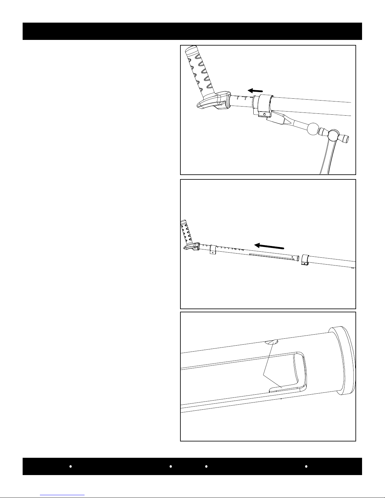
Firmly grab the left handlebar (#A5171)
and pull it completely out of the tube.
Step 5:
Push the tabs of handlbar inner tube end
plug (#A5134) inward to dislodge it from
the handlebar tube.
Step 6a:
Altri manuali per STEP ONE
1
Questo manuale è adatto per i seguenti modelli
1
Indice
Altri manuali SCIFIT Macchina passo-passo