Sea-Bird Scientific SBE 25plus Manuale utente

User manual
SBE 25plus Sealogger CTD
Conductivity, Pressure, Temperature Recorder
Document No. SBE25plus
Release Date: 2021-09-27
Version: A
Firmware: 1.0 & up
Software: Seasoft V2
425-643-9866
seabird.com


Table of Contents
Section 1 SBE 25plus quick start guide........................................................................................ 3
Section 2 Specifications.................................................................................................................... 5
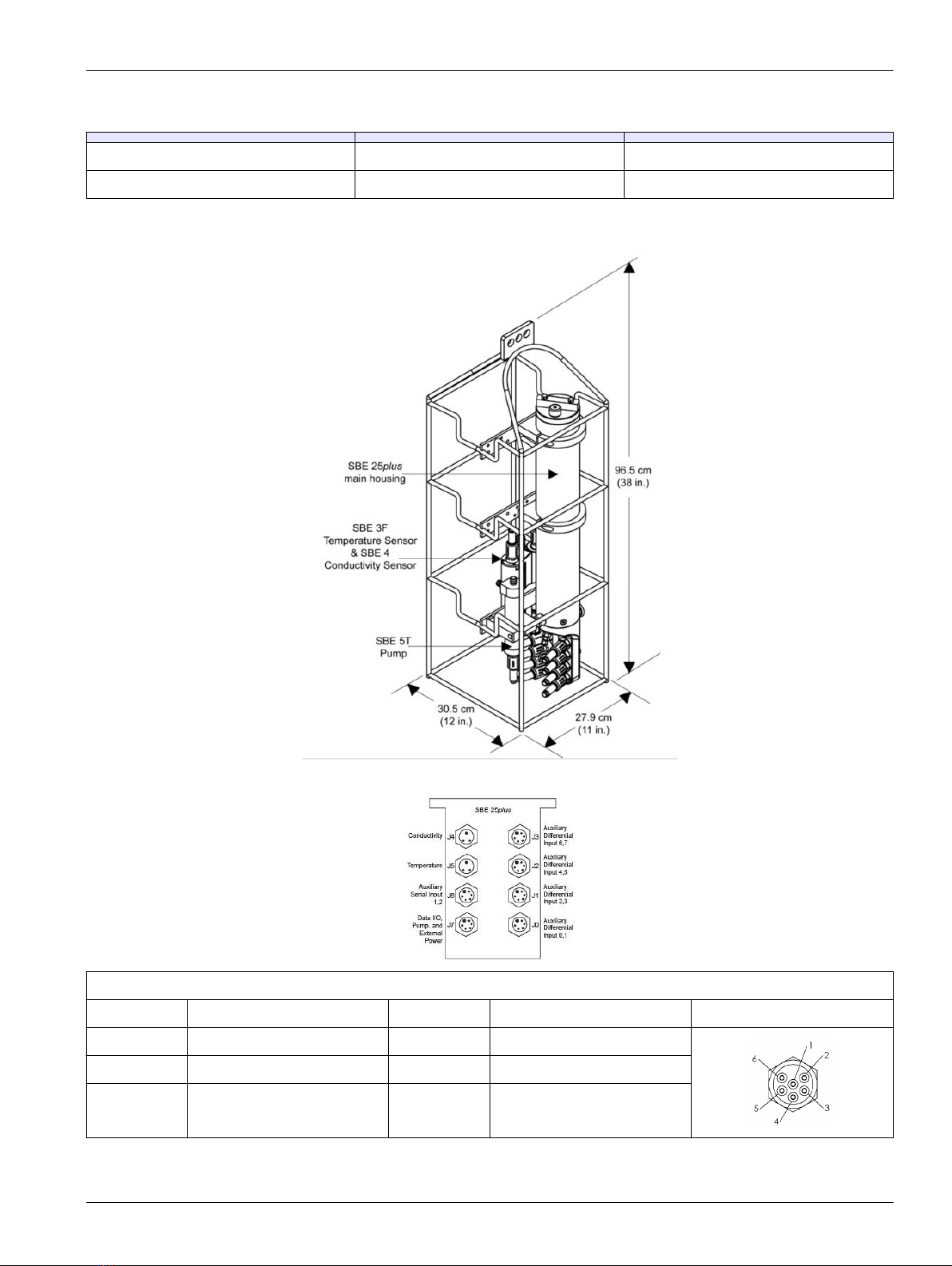
2.1 Mechanical................................................................................................................................... 5
2.1.1 Dimensions..........................................................................................................................5
2.1.2 Connectors and cables........................................................................................................5
2.2 Communications.......................................................................................................................... 8
2.3 Electrical....................................................................................................................................... 8
2.4 Analytical...................................................................................................................................... 8
Section 3 Overview............................................................................................................................. 9
3.1 Integration with other equipment for real-time data collection...................................................... 9
3.2 Integration with other equipment for autonomous operation...................................................... 11
Section 4 Set up sensor and verify operation............................................................................ 13
4.1 Software menu items................................................................................................................. 14
4.2 Communication troubleshooting................................................................................................. 14
4.3 Prepare the 25plus for vertical or horizontal deployment........................................................... 15
4.3.1 Vertical deployment........................................................................................................... 15
4.3.2 Horizontal deployment.......................................................................................................16
4.4 External power and cable length................................................................................................ 16
4.5 Battery pack............................................................................................................................... 17
4.6 Plunger switch............................................................................................................................ 19
Section 5 Deployment and recovery.............................................................................................21
5.1 Set up for deployment................................................................................................................ 21
5.1.1 Example setup...................................................................................................................22
5.2 Pump operation.......................................................................................................................... 23
5.3 Real-time data setup.................................................................................................................. 23
5.4 Real-time data collection............................................................................................................ 24
5.4.1 Standard output format .....................................................................................................25
5.4.1.1 Equations to write user-made software.................................................................... 25
5.4.2 Real-time data collection with a Deck Unit........................................................................ 27
5.4.3 Output format for autonomous water sampler................................................................... 27
5.5 Recommendations for quality data............................................................................................. 27
5.6 Recover 25plus from deployment.............................................................................................. 28
Section 6 Transmit and convert data........................................................................................... 29
6.1 Transmit data with RS232.......................................................................................................... 29
6.2 Transmit data with USB ............................................................................................................ 30
6.3 Convert data............................................................................................................................... 30
Section 7 Maintenance..................................................................................................................... 31
7.1 Corrosion precautions................................................................................................................ 31
7.2 Plumbing.................................................................................................................................... 31
7.3 Clean pressure sensor............................................................................................................... 31
7.4 Conductivity cell......................................................................................................................... 32
7.5 Disassemble and reassemble TC duct...................................................................................... 32
7.6 Replace batteries....................................................................................................................... 34
7.7 Clean bulkhead connectors........................................................................................................ 36
7.8 Examine O-rings........................................................................................................................ 38
7.9 Calibration.................................................................................................................................. 38
7.9.1 Conductivity....................................................................................................................... 38
7.9.2 Pressure............................................................................................................................ 38
7.9.3 Temperature...................................................................................................................... 39
7.10 Spare parts and accessories.................................................................................................... 39
1

Section 8 Reference: command descriptions............................................................................ 41
8.1 Status......................................................................................................................................... 41
8.2 General setup............................................................................................................................. 46
8.3 Pump setup................................................................................................................................ 46
8.4 Voltage sensor setup................................................................................................................. 47
8.5 Serial sensor setup.................................................................................................................... 47
8.6 Real-time output setup............................................................................................................... 48
8.7 Serial sensor setup.................................................................................................................... 49
8.8 Data upload................................................................................................................................ 50
8.9 Test commands.......................................................................................................................... 50
8.10 Calibration coefficients............................................................................................................. 51
8.11 Hardware configuration............................................................................................................ 52
Section 9 Serial sensor integration.............................................................................................. 53
9.1 Command descriptions.............................................................................................................. 53
9.1.1 Set up and store data for unknown serial sensor.............................................................. 54
9.1.2 Set up and store Triplet data............................................................................................. 55
9.1.3 Set up and store SeaOWL data........................................................................................ 55
9.1.4 Set up and store SUNA data............................................................................................. 56
9.1.5 High current-draw sensor integration................................................................................ 57
Section 10 Troubleshooting........................................................................................................... 59
10.1 No communications with sensor.............................................................................................. 59
10.2 No data recorded..................................................................................................................... 59
10.3 Cannot see data in Seasave software..................................................................................... 59
10.4 Scan length error...................................................................................................................... 59
10.5 Bad data................................................................................................................................... 59
10.6 Cannot use the USB to communicate...................................................................................... 60
Section 11 General information..................................................................................................... 61
11.1 Service and support................................................................................................................. 61
11.2 Waste electrical and electronic equipment............................................................................... 61
11.3 China RoHS disclosure table................................................................................................... 61
Table of Contents
2

Section 1 SBE 25plus quick start guide
This quick start guide gives the steps necessary to make sure that the SBE 25plus
operates correctly and collects data before it is deployed.
What's in the box:
• CD or memory stick—has software, calibration files, documentation
• Dummy plug and lock collar
• Data I/O cable to connect the sensor to a PC
• Spare hardware and O-ring kit.
1. Install the manufacturer-supplied software on a PC (refer to Set up sensor and verify
operation on page 13 for details.)
2. Connect the data I/O cable to the sensor and the PC and double-click on
SeaTermV2.exe to start the software.
3. Set up the sensor for deployment.
a. If necessary, make sure that all data stored in the sensor is transmitted to a PC.
b. Set the date and time and configure the data collection settings.
c. Send the DS and DC commands to verify setup.
4. Remove the yellow protective label from the plumbing intake and exhaust.
5. Deploy the sensor. For most applications, make sure the connector is at the bottom
(lowest point).
6. Immediately after the sensor is recovered from a deployment:
a. Use the software to turn off the sensor.
b. Flush the sensor with fresh water.
c. Keep the sensor out of direct sunlight between deployments.
7. Transmit data from the sensor to a PC. Refer to Transmit and convert data
on page 29 for details.
8. Refer to Recover 25plus from deployment on page 28 for details to prepare the
sensor for short- or long-term storage.
3

SBE 25plus quick start guide
4

Section 2 Specifications
2.1 Mechanical
Weight, 600 m, plastic, in air, water Weight, 6800 m, titanium, in air, water Cage, in air, water
20.0, 11.5 kg 22.5, 13.5 kg 6.7, 5.9 kg
2.1.1 Dimensions
2.1.2 Connectors and cables
J3 auxiliary differential input 6, 7
Contact Function Contact Function MCBH6MP
1 Common 4 Voltage 7 signal
2 Voltage 6 signal 5 Voltage 7 common
3 Voltage 6 common 6 Auxiliary power out
5

J2 auxiliary differential input 4, 5
Contact Function Contact Function MCBH6MP
1 Common 4 Voltage 5 signal
2 Voltage 4 signal 5 Voltage 5 common
3 Voltage 4 common 6 Auxiliary power out
J1 auxiliary differential input 2, 3
Contact Function Contact Function MCBH6MP
1 Common 4 Voltage 3 signal
2 Voltage 2 signal 5 Voltage 3 common
3 Voltage 2 common 6 Auxiliary power out
J0 auxiliary differential input 0, 1
Contact Function Contact Function MCBH6MP
1 Common 4 Voltage 1 signal
2 Voltage 0 signal 5 Voltage 1 common
3 Voltage 0 common 6 Auxiliary power out
Connector Contact Function MCBH3MP
J4 Conductivity 1 Common
2 Conductivity frequency
3 Auxiliary power out
Connector Contact Function MCBH3MP
J5 Temperature 1 Common
2 Temperature frequency
3 Auxiliary power out
J6 auxiliary serial input 1, 2
Contact Function Contact Function MCBH6MP
Specifications
6

1 Common 4 Serial 2 data RX
2 Serial 1 data RX 5 Serial 2 data TX
3 Serial 1 data TX 6 Auxiliary power out
J7 data I/O, pump, external power
Contact Function Contact Function MCBH6MP
1 Common 4 Pump power common
2 RS232 data RX 5 Pump power
3 RS232 data TX 6 Auxiliary power in,
14–20 VDC
Figure 1 Y cable
Figure 2 Data I/O cable
Figure 3 SBE 4 to CTD cable
Notes:
• The Y cable from J7 connects to the pump and a data I/O power cable, so the system
can connect to a PC for setup and to transmit data, and to externally power the
25plus.
•Auxiliary sensors that draw more than 1 amp, even momentarily, must be
connected to J3 or J6. Refer to High current-draw sensor integration
on page 57 for details.
Specifications
7

2.2 Communications
Memory 2 GB
Communication interface RS232
Data collection rate 16 Hz
2.3 Electrical
Input from external power supply 14–20 VDC
Current draw, operation (no auxiliary sensors or pump) 95 mA
Current draw, pump 150 mA
Current draw, communications 70 mA
Current draw, low power (powered by internal batteries) 70 µA
Current draw, low power (powered by external batteries) 175 µA
2.4 Analytical
Parameter Range Accuracy Resolution
Conductivity 0–70 mS/cm ±0.003 mS/cm 0.0001 mS/cm
Temperature -5–35 °C ±0.002 °C (-5–35 °C) 0.0001 °C
Pressure various to 7000 m ±0.1% full scale range 0.002% full scale range
Specifications
8
Indice
Altri manuali Sea-Bird Scientific Registratore di dati


