SealMaster MasterMix Bulk Manuale utente


S:\Engineering\13-Operator Manuals\Current\BULK TANKERS_V2.0_OCT_2021.docx
MASTERMIX™BULK STORAGE TANKS
Owner’s Manual
Version 2.0
Issue Date: May 2021
Effective Date: October 2021
Version
Date
Changes
Approval
1.0
5/21
Original Issue
DS
2.0
10/21
Motor - Material
JG

Table of Contents
CORRESPONDENCE .......................................................................................................................................4
SealMaster® LIMITED WARRANTY................................................................................................................5
SAFETY PRECAUTIONS AND CAUTIONS ........................................................................................................6
PRECAUTIONS ...........................................................................................................................................6
CAUTIONS .................................................................................................................................................6
STARTUP........................................................................................................................................................7
1-STARTING THE ENGINE-HONDA.............................................................................................................7
2- BEFORE STARTING THE ENGINE-VANGUARD .......................................................................................8
3- STARTING THE ENGINE .........................................................................................................................8
4-AGITATOR ..............................................................................................................................................9
5-MATERIAL PUMP .................................................................................................................................10
MACHINE OPERATION ................................................................................................................................11
6-DISCHARGE MATERIAL OUT OF TANK..................................................................................................11
7-FILL MATERIAL IN TANK.......................................................................................................................12
MACHINE MAINTENANCE...........................................................................................................................13
MAINTENANCE SCHEDULE......................................................................................................................13
MAINTENANCE SCHEDULE –STEIN-O-GLAND ........................................................................................14
TROUBLESHOOTING GUIDE ....................................................................................................................15
TROUBLESHOOTING GUIDE-CHART........................................................................................................17
TANK CAPACITY CHART...............................................................................................................................18
MATERIAL DEPTH AND GALLON VOLUME..............................................................................................18
MACHINE PICTURES AND PARTS LIST .........................................................................................................20
PARTS LIST PICTURE-1 TANK...................................................................................................................20
PARTS LIST PICTURE-2 OPTIONAL ...........................................................................................................21
PARTS LIST PICTURE-3 STANDARD..........................................................................................................22
PARTS LIST PICTURE-4 STANDARD..........................................................................................................23
PARTS LIST PICTURE-5 OPTIONAL ...........................................................................................................24
PARTS LIST PICTURE-6 STANDARD & OPTIONAL.....................................................................................25
PARTS LIST PICTURE-7 PUMP W/ ELECTRIC MOTOR OPTIONAL.............................................................26
PARTS LIST PICTURE-8.............................................................................................................................27
PARTS LIST PICTURE-9.............................................................................................................................28
ROPER 2” PUMP 3617 HZ............................................................................................................................30
PARTS LIST...............................................................................................................................................30

3
PARTS LIST FOR 2” BOWIE PUMP OPTIONAL..........................................................................................31
PARTS LIST FOR 3” BOWIE PUMP OPTIONAL..........................................................................................33
PARTS LIST FOR 2” ARO PUMP OPTIONAL..............................................................................................34
PARTS LIST FOR SMALL-DIAPHRAGM PUMP...........................................................................................38
PARTS LIST FOR LARGE-DIAPHRAGM PUMP...........................................................................................40
PARTS FOR ELECTRICAL SET-UP ..................................................................................................................41
PARTS FOR PLUMBING..................................................................................................................................1
PICTURE-1 AGITATION ..............................................................................................................................1
PICTURE-2-CONTROL VALVES ...................................................................................................................2
PICTURE-3 3” BOWIE & HIGH SPEED MOTOR...........................................................................................3
PICTURE-4 FILTER PLUMBING ...................................................................................................................4
PICTURE-5 PUMP WITH C-FACE MOTOR ..................................................................................................5
PICTURE-6 PUMP WITH GAS ENGINE........................................................................................................6

4
ThorWorks Industries, Inc.
Purchased by __________________________ Model NO. _______________________
Company Name _______________________ Serial NO. _______________________
Address ________________________________ Acceptance Date ________________
City _____________ State______ Zip _______
CORRESPONDENCE
All Correspondence regarding this equipment, as well as general correspondence should be addressed to:
ThorWorks Industries, Inc.
PO Box 2277
Sandusky, OH 44870
In referring to the equipment, kindly state the Model Number, Serial Number and any part number involved
`

5
SealMaster® LIMITED WARRANTY
SealMaster warrants that its products are of quality material and workmanship. SealMaster
agrees to replace, within a period of one (1) year from date of delivery, or at its option, repair,
without charge, any part of their manufacture which proved defective. The repair or
replacement will be free of charge F.O.B. Sandusky, Ohio, providing the damaged part or parts
are returned, freight prepaid, to SealMaster and investigation shows such repair or
replacement is made necessary by an inherent defect of material or workmanship.
It is hereby understood that engines, motors, pumps, or other components purchased by
SealMaster for use on its equipment are not warranted by SealMaster and are sold only with
the standard warranty of the manufacturer of that component.
SealMaster will make no allowances for repairs or alterations completed by outside sources
unless authorization is in writing and approved by an authorized SealMaster representative.
Any claims for defective material or workmanship must be made prior to the expiration of thirty
(30) days from the date failure occurs, and in all cases prior to the expiration of the warranty
period of one (1) year. It is the intent of this paragraph to limit SealMaster’s liability solely to
the cost of replacement parts, F.O.B. factory, or at the option of SealMaster to repair of the
defective part or parts. No allowances for damages, lost time, or any other claim will be
recognized.
This warranty is null and void if other than genuine SealMaster parts are used.
SealMaster is constantly striving to improve their products. Changes in design and
improvement will be made whenever the manufacturer believes the efficiency of the product
will be improved, without incurring any obligation to incorporate such improvements in any
machines which have been shipped or are in service.
In an effort to continue to improve product quality, SealMaster reserves the right to change
specifications without notice.
Any modification or alteration of this machine without prior approval of the manufacturer may
void this warranty.

6
SAFETY PRECAUTIONS AND CAUTIONS
PRECAUTIONS
Always wear eye and ear protection, and gloves.
Be aware of all CAUTION, WARNING, and DANGER signs on the
unit.
Read all Owners Manuals that come with this unit.
Make sure the operator is familiar with the units’ operation.
Replace any hoses that show signs of wear, fraying, or splitting.
Be sure all fittings and joints are tight and leakproof.
Check all the nuts and bolts for tightness. Bolts and nuts are
machined tightened before leaving the factory. However, some
loosening may occur during shipment.
Do not do maintenance work on the machine while in operation.
The machine should not be left unattended when running.
CAUTIONS
Keep hands, feet, and clothing away from moving parts.
Do not operate the machine without all guards in place.
Do not operate Agitator with the chain guard removed.
Do not operate Agitator with Manhole cover open.
Open Manhole cover before pumping material out. This Tank is
equipped with an Air Vent and operating a Pump with the lid
closed may create a vacuum if the vent is plugged.

7
MASTERMIX™STORAGE TANKS
EQUIPPED WITH HONDA ENGINE
STARTUP
1- BEFORE STARTING THE ENGINE-HONDA
Note: Make sure you check the appropriate oil level.
Check Hydraulic Oil –Maintain level at 4 inches below tank top,
when COLD. See Hydraulic Oil in this section for proper oil grade.
Make certain the shut-off valve on the tank is open.
Check gas supply.
Be sure all hydraulic valves are in a neutral position.
STARTING THE ENGINE
Set the fuel shutoff and choke levers to the on position.
Set the throttle lever at ½ open.
Turn the engine switch to the start position.
It is important that when you are done running the engine that
the fuel shutoff lever is turned to the off position. This keeps
gasoline from mixing with the oil.
ENGINE
SWITCH
CHOKE
FUEL
THROTTLE

8
MASTERMIX™STORAGE TANKS
EQUIPPED WITH VANGUARD ENGINE
OPERATING INSTRUCTIONS
STARTUP
2- BEFORE STARTING THE ENGINE-VANGUARD
Note: Make sure you check the appropriate oil level.
Check Hydraulic Oil –Maintain level at 4 inches below tank top, when COLD. See
Hydraulic Oil in this section for proper oil grade. Make certain the shut-off valve
on the tank is open.
Check gas supply.
Be sure all hydraulic valves are in a neutral position.
3- STARTING THE ENGINE
Set the throttle and choke levers to the on position.
Set fuel shut-off to the on position.
Set the engine on/off switch to run position.
Start the engine.
It is important that when you are done running the engine that the fuel shutoff
lever is turned to the off position. This keeps gasoline from mixing with the oil.
CHOKE
FUEL SHUT-OFF
ON/OFF
STARTER
SWITCH
FUEL TANK
ENGINE
CORD
HANDLE
THROTTLE
CONTROL
9
MASTERMIX™STORAGE TANKS
OPERATING INSTRUCTIONS
STARTUP
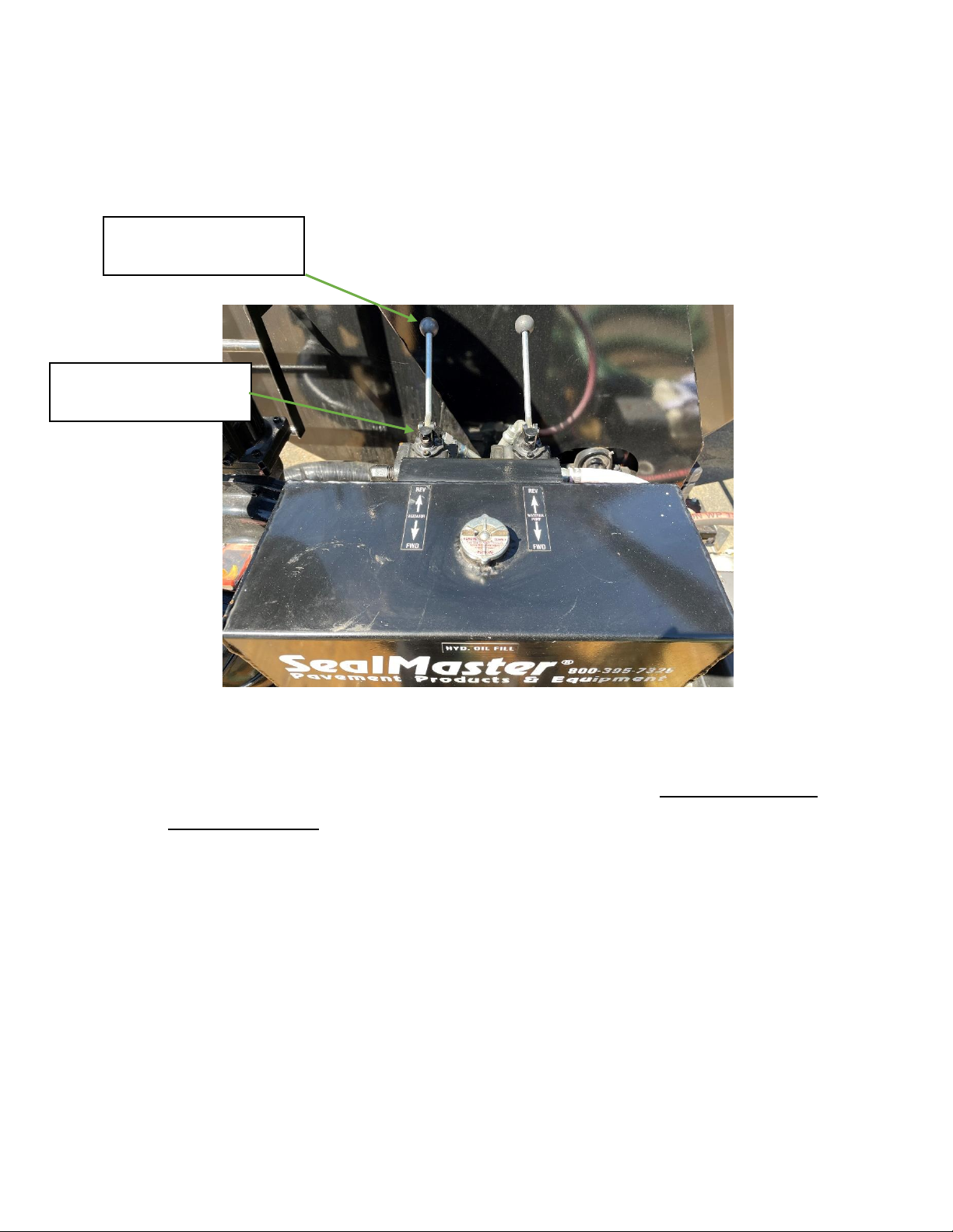
4-AGITATOR
The agitator can operate in either direction. The agitator control
hydraulic valve #19 meters oil flow, which means how far the
lever handle is moved, determines rotation speed. Material left in
the tank should be agitated 10 to 15 minutes. Do not leave a sand
and sealer mixture in the tank without agitation for more than
one day.
19 AGITATOR
CONTROL HYDRAULIC
VALVE
AGITATOR CONTROL
LEVER HANDLE
Indice


