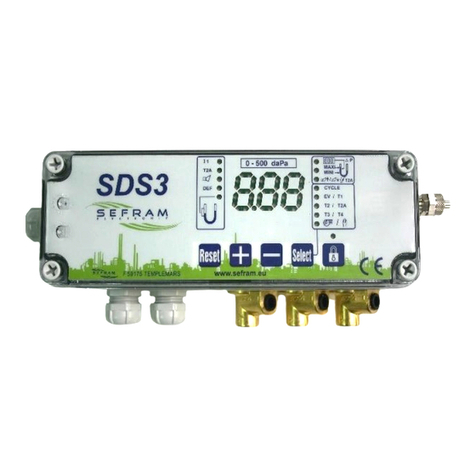
SEFRAM SPX100 Manuale utente

SPX100 SENSOR
DUST EMISSIONS CONTROLLER
Notice Technique
FI 72.0110.0316E
Page 1 sur 27
SPX 100 V4
TECHNICAL NOTICE

SPX100 SENSOR
DUST EMISSIONS CONTROLLER
Notice Technique
FI 72.0110.0316E
Page 2 sur 27
SUMMARY
I) GENERALITIES page 3
II) CHARACTERISTICS page 4
III) CONNECTIONS page 5
IV) RUNNING page 8
1) General
2) Alarm
3) 4-20 mA
4) Connection
V) ADJUSTMENTS page 10
1) Front panel
2) Adjustments menu
3) Measure reading adjustment
4) Password adjustment (or CODE)
5) Date and time adjustment
6) Setting the unit
7) Setting the display format
8) View measuring scale
9) Setting the 4-20 mA scale
10) Alarm average duration adjustment
11) Auto sensitivity
12) Auto zero
13) Average calculation
14) Calibration
15) Language adjustment
16) Alarm adjustment / Alarm reading
VI) INSTALLATION / START page 22
VII) CALIBRATION PRINCIPLE page 22
VIII) General instructions for safety, assembly, page 23
commissioning, usage and maintenance
IX) WARRANTY page 24
X) CERTIFICATE page 24
XI) PHYSICAL DIMENSIONS page 25
1) Sensor
2) Control unit

SPX100 SENSOR
DUST EMISSIONS CONTROLLER
Notice Technique
FI 72.0110.0316E
Page 3 sur 27
I) GENERALITIES
The SPX monitors and displays the dust emission behind a filter, based on the
triboelectric effect. It’s made with two main units self connected. It gives the trend of dust
emissions as a % or as a quantity (mg/m3or other).
- The sensor: - installed in the duct or the duct to be monitored
- its extremity is projected into the particle flow
- monitored the signal
- The control unit : - receives the data from the sensor
- averaging measure
- converses with the user (display, keys)
- automatic zero calibration
- stores and dates the datas (1 month of recordings)
- commands the alarm
- an output 4-20 mA (in option) of the trend
The SPX 100 can be connected with a PC (line RS232 and software in option) directly or
through a telephone MODEM
- remote viewing / configuration
- reading of the stored datas
- graph operation, reports creation, etc ...
- storage in disk files format
- graph display in continuous (real time)

SPX100 SENSOR
DUST EMISSIONS CONTROLLER
Notice Technique
FI 72.0110.0316E
Page 4 sur 27
PRINCIPLE PLAN :

SPX100 SENSOR
DUST EMISSIONS CONTROLLER
Notice Technique
FI 72.0110.0316E
Page 5 sur 27
II) CHARACTERISTICS
- Supply 115V or 230V
10%
- Frequency 50-60 Hz
- Power consumption 12 VA
- Relay contact parameters Single pole changeover - 1A - 250V AC1
- Parameters adjustment By keys on front panel with the user password
- Display On alphanumerical LCD display + backlight /
Leds bargraph
- Device protection
By fuse 500 mA
- Operating temperature
* part outside the duct: 0 à 65° C
* in the flow at the sensor: < 85° C standard sensor
250° C sensor with thermal separator
> 250° C - please contact us
- Storage temperature - 20 to 70° C
- Alarm threshold Adjusting from 0 to full scale
(shown in alarm adjustment)
- Averaging measure From 1 to 60 minutes
- Calendar Retention 11 years (without supply)
Accuracy +/- 1 minute per month maxi
Leap year / year 2000
- 1 month memory Save by battery (kind : R6)
Retention 10 years (without supply)
- Display unit µg/m3, mg/m3 or % full scale
- Cable length sensor / base 10 meter in standard (2)
- Sensor length 200 mm in standard (2)
- 4-20 mA (1) Incorporated supply (active) NOT INSULATED
Maxi load 500 ohms
- PC connection (1) RS232
(1) : in option
(2) : other on request

SPX100 SENSOR
DUST EMISSIONS CONTROLLER
Notice Technique
FI 72.0110.0316E
Page 6 sur 27
III) CONNECTIONS
1) Sensor
The sensor is fitted on the duct or the duct to be monitored:
- Filetage 1" BSP (26-34 GAS)
- Placed on a rectilinear position (5 diameters before / 2 diameters after mini -
N.B. : If stack : 5 diameters after)
- grounded metallic duct (5 meters before the sensor mini). The continuity of earth
between the sensor and the section of casing must be ensured.
- The sensor length must be adjusted to the duct.

SPX100 SENSOR
DUST EMISSIONS CONTROLLER
Notice Technique
FI 72.0110.0316E
Page 7 sur 27
2)Base
To access the terminal blocks, put off the connections cover
NOTE : The relay contacts are drawing main supply « off ».
When the supply voltage comes « on », the relay pulls up if no alarm.
FUSE PROTECTION

SPX100 SENSOR
DUST EMISSIONS CONTROLLER
Notice Technique
FI 72.0110.0316E
Page 8 sur 27
* SUPPLY CHOICE
(To access this, put off the front panel and the upper board)
BE CAREFUL : The SPX 100 leaves our workshops for a 230V supply voltage.
WARNING :
If you change the supply voltage, you must update the data plate located on the outside of the box.

SPX100 SENSOR
DUST EMISSIONS CONTROLLER
Notice Technique
FI 72.0110.0316E
Page 9 sur 27
IV) RUNNING
1) General
A measure, always made by the sensor, is transmitted to the base to be interpreted and
stored.
The base has two types of memory :
- A working memory :
Refreshed each second
Calculate the average measure on an adjustable duration from 1 to 60 minutes
- A storage memory (in option) :
Stores the last 1 month datas (scrolling memory)
1 storing each minutes
To calculate the average value of the dust concentration on 1 month maxi
(see « average calculation on 24 hours »)
Possibility to read the datas via a PC :
- Incident analysis
- graphics outputs
- Report outputs
- etc ...
Display of the instantaneous and averaged trend (from 1 to 60 mm) in mg/m3, µg/m3or %
of full scale (see «measure reading adjustment»).
If the mg/m3or µg/m3unit is choiced, it's necessary to calibrate the device with a known
or estimated dust concentration (e.g. mass measurement).
All the adjustments need a user password (adjustable).

SPX100 SENSOR
DUST EMISSIONS CONTROLLER
Notice Technique
FI 72.0110.0316E
Page 10 sur 27
2) Alarm
The SPX 100 has an adjustable alarm threshold (see « alarm adjustment »).
Each time, the averaging value (1 to 60 min) is compared with the alarm threshold, the
alarm is activated when the average is above the alarm threshold :
- The DEFAULT relay pulls down
- The « bargraph » on front panel is flicking
The alarm is even held if the measure downs again the alarm threshold.
To cancel the alarm, the user must :
- Press the « alarm » key and keep it pressed
- Press the « valid » key (see « alarm adjustment »)
(option of a non maintained alarm: please consult us)
3) 4-20 mA (in option)
The 4-20 mA output scale is adjustable.
The 4-20 mA output recopies the instantaneous measure or the average measure according
to the display (see « measure reading adjustment »).
4 mA for 0 measure,
20 mA for the value of the 4-20 mA input scale.
4) Connection
Each time the base communicates with the sensor via a bi directional digital data link. If
there is a problem (cutted cable, bad connections, component failure), this message
appears: CONNECTION FAULT
SENSOR
In this case, the 4-20 mA output becomes à 0 mA and the DEFAULT relay pulls down.
This message disappears if there is no problem.
Questo manuale è adatto per i seguenti modelli
1
Indice
Altri manuali SEFRAM Controllori