www.selbit.pl 3
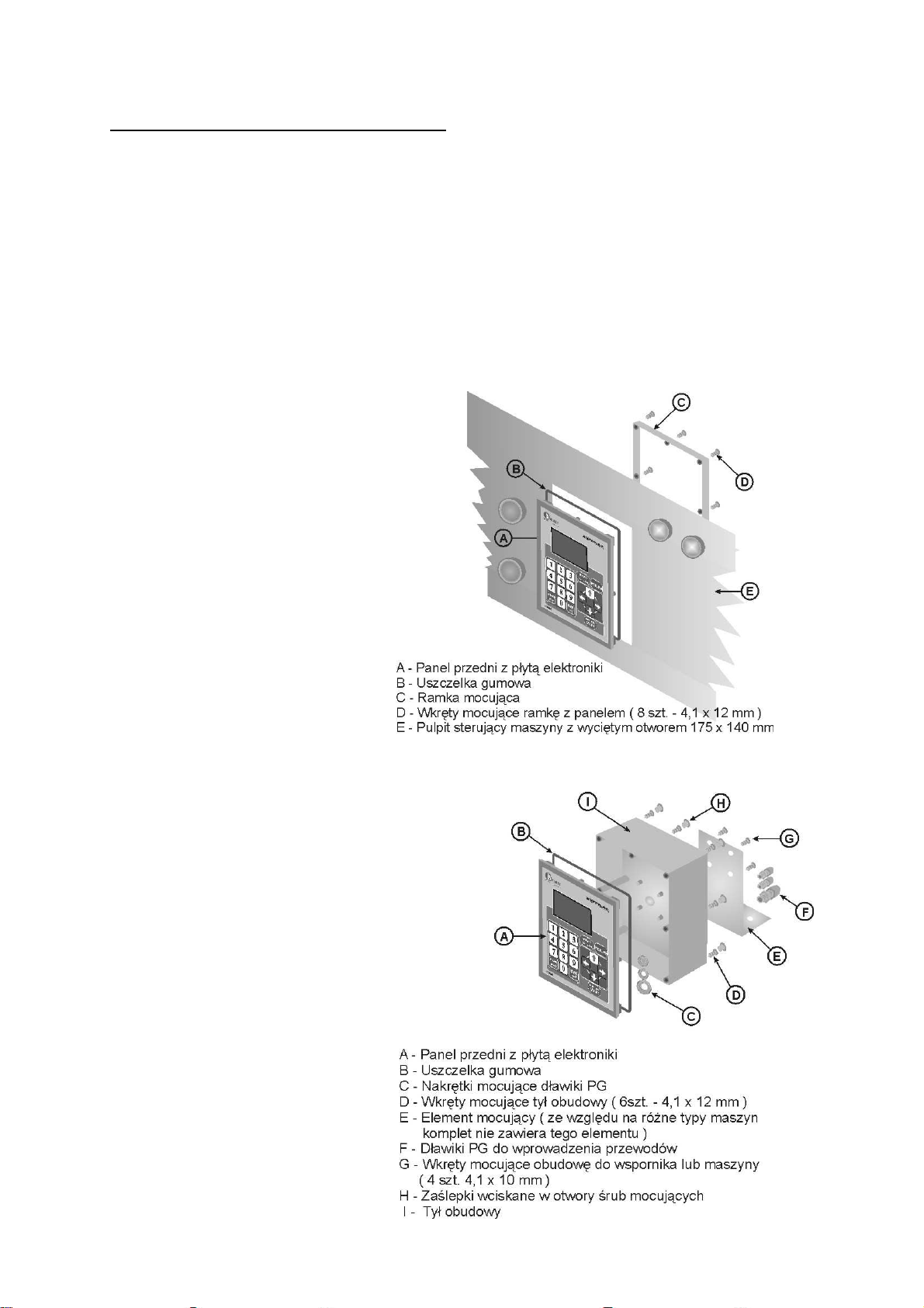
When the controller is installed as a stand-alone device, one can after the installation screw it
directly on the machine with 4 units of 4.1 x 10 screws included in the set, or, if necessary,
make an additional installation element, which after screwing it on to the case will serve as a
distance support.
(2) Electrical installation
CAUTION!
Because of the risk of electric shock, all connections shall be performed only
when the machine is disconnected from power. The best way to do that is to
turn off the main switch of the machine.
All connections should be done with double-insulated cables, intended for controlling
devices powered from 230V AC network. The cables which enter the case ought to be
round, with the diameter adjusted to the chokes installed in the back of the case.
Endings of the cables should cleaned and have sleeves, or be tinned before screwing.
This is important for correct and fail-safe operating of the controller in the future.
In order to assure correct and fail-safe operation, the wiring ought to be performed in
accordance with the following instructions. Incorrect wiring can result in disturbing the
work of the controller, and thus impeding its operation.
The machine, in which the controller is installed, should have operational limit
switches, and feed contractors ought to have a blockade preventing both of
them to be turned on at once!
(3) Installation of the TSS-8/24 power transformer
TheTSS-8/24 230/24V power transformerincluded in the set ought to be installed in the
power supply cabinet of the machine.
The transformer is intended for a standard TSS-35 fixing rail, commonly used in electric
machines. The location of the transformer ought to be maximally away from other electric
elements (electrical converters, contractors, other transformers). It is important, because
otherwise electromagnetic noise may penetrate the electronic system of the controller through
the transformer.
The cables providing 230V power should be connected to the transformer clamps marked as
PRI 230V. The transformer should be installed in the circuit which includes neither
contractor inductors nor an inverter.
230V power cables ought to be laid as far from other cables in the cabinet as possible.
The cables transmitting power to the electronic board should be connected to the transformer
clamps marked as SEC 24V. Similarly as in the previous connection, these cables ought to be
laid as far from other cablesas possible, including the 230V cables powering the transformer.
Length of the power cables (24V) should be adequate to the location of the controller.
The cables going from the SEC 24V transformer clamps should in the final stage of the
installation be connected to controller board clamps marked as PWR.
(4) Installation of the interference suppressors (CPZ)