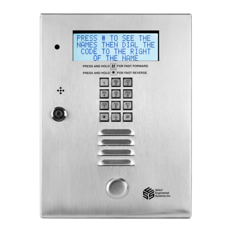
Select Engineered Systems Select Gate 1A Manuale utente

This page intentionally blank.

i
.TABLE OF CONTENTS
1.0 INTRODUCTION TO SELECT GATE .............................................. 1
1.1 STANDARD FEATURES .................................................................. 2
1.2 SPECIAL FEATURES ...................................................................... 3
1.3 OPTIONS ....................................................................................... 3
1.4 ENVIRONMENTAL CONSIDERATIONS ......................................... 3
1.5 ELECTRICAL ................................................................................. 3
1.6 TECHNICAL DATA ......................................................................... 4
2.0 INSTALLATION INSTRUCTIONS .................................................... 5
3.0 WIRING HOOKUP CONNECTIONS ................................................ 6
3.1 INSTALLATION PROCEDURE ........................................................ 7
3.1.1 MOUNTING SELECT GATE ............................................................ 7
3.1.2 GROUNDING SELECT GATE .......................................................... 8
3.1.3 CONNECTING POWER TO SELECT GATE ................................... 9
3.1.4 TELEPHONE CABLES TO USE TO WIRE SELECT GATE............ 10
3.1.4.1 CONNECTING RJ-31X .......................................................... 11
3.1.4.2 CONNECTING TO HOMES WITH ALARM SYSTEM .......... 12
3.1.5 CONNECTING DEVICES TO CONTROL RELAY ........................... 13
3.1.6 REX INPUT ....................................................................................... 14
3.1.7 ADJUSTING SPEAKER VOLUME ................................................... 15
3.1.8 ADJUSTING MICROPHONE SENSITIVITY .................................... 16
3.1.9 CHANGING SELECT GATE LIGHT BULB ...................................... 17
4.0 INITIALIZATION AND PROGRAMMING ......................................... 18
4.1 CONFIGURING SELECT GATE ...................................................... 18
4.2 FACTORY DEFAULTS AND PROGRAMMING FUNCTIONS ......... 19
4.2.1 PIN CODES .................................................................................... 20
4.2.2 PHONE CODES ............................................................................. 20
4.2.3 RELAY 1 UNLOCK TONE ............................................................... 21
4.2.4 RELAY 1 LATCH TONE.................................................................... 21
4.2.5 RELAY 1 ONE HOUR TONE ...... .................................................... 21
4.2.6 RELAY 1 OPEN TIME ..................................................................... 21
4.2.7 STRIKE OUT COUNT ..................................................................... 22
4.2.8 LOCK OUT TIME ........................................................................... 22
4.2.9 RELAY 2 UNLOCK TONE ............................................................... 22
4.2.10 RELAY 2 LATCH TONE ................................................................. 23
4.2.11 RELAY 2 ONE HOUR TONE ........................................................... 23
4.2.12 RELAY 2 OPEN TIME .................................................................... 23

ii
TABLE OF CONTENTS
4.2.13 RING TYPE ........................................................................... 24
4.2.14 RING COUNT ........................................................................ 24
4.2.15 CALL WAITING TYPE .......................................................... 25
4.2.16 RING DETECT ....................................................................... 25
4.2.17 BACK BEEP ........................................................................... 25
4.2.18 TALK TIME ............................................................................ 26
4.2.19 KEYPAD ON .......................................................................... 26
4.2.20 PROGRAMMING PASSWORD ............................................. 26
4.2.21 CALL FORWARD TONE ........................................................ 26
4.4.22 CALL FORWARD TYPE ......................................................... 26
4.2.23 CALL FORWARD ON/OFF ..................................................... 27
4.2.24 CALL FORWARD NUMBER ................................................. 27
4.2.25 CLEAR ALL PHONES ........................................................... 27
4.2.26 CLEAR ALL PINS .................................................................. 27
4.2.27 PRESET ALL RELAYS .......................................................... 27
4.2.28 CLEAR ALL CALL FORWARD PARAMETERS ................... 28
4.2.29 PRESET ALL MEMORY ........................................................ 28
4.3 EXITING PROGRAMMING MODE ..................................................... 28
5.0 SELECT GATE OPERATION ........................................................... 29
5.1 SELECT GATE CALLING HOUSE .................................................. 29
5.2 SELECT GATE CALLING HOUSE WHEN PHONE IN USE .......... 30
5.3 SELECT GATE CALLING OUTSIDE PHONE ................................. 30
5.4 SELECT GATE USING PIN CODES ............................................... 31
5.5 CALLING SELECT GATE FROM HOUSE ...................................... 31
5.6 PROGRAMMING SELECT GATE FROM HOUSE .......................... 32
5.6.1 PROGRAMMING SELECT GATE FROM OUTSIDE PHONE ........ 32
5.6.2 EXITING PROGRAMMING MODE ................................................... 32
APPENDIX A SETUP INFORMATION ....................................................... 33 - 35
APPENDIX B QUICK PROGRAMMING GUIDE ....................................... 36
APPENDIX C SELECT GATE CONFIGURATION GUIDE........................... 37

SELECT GATE SG-1A V1.X
SELECT ENGINEERED SYSTEMS 11/01 1
1.0 INTRODUCTION TO SELECT GATE
The SelectGateisaproductthatactsasanintercomandaccesscontrolsystem. TheSelect
Gate, when started, intercepts a telephone company phone line and initiates a calling/ringing
sequence to the telephone set equipment (up to 5 phones of standard ringer equivalence) in the
house or residence. It then provides a voice communication channel from the Select Gate to the
telephone set.
If the telephone company line is in use at the time of activation, or if the Select Gate is
communicating toatelephonesetwhenanexternallygeneratedringsignalisdetected,anindicating
tone will be placed on the telephone set line at the house or residence. The access management
functions are controlled via DTMF (Touch-Tone™) signaling.
The Select Gate is activated by
pressing the call button or the "#" on the
keypad. Select Gate tones will be
provided to alert the caller of system
operation.
For dialing outside numbers
(other than the house or residence) the
Select Gate is a microprocessor based
device that will allow entering 1 digit. It
then automatically dials the phone
number that was programmed into
memory. The Select Gate provides a
relay output for controlling doors, gates,
or any device actuated by a contact
closure or contact opening. The Select Gate has programmable 1 to 9 minute talk-time limit, with
warning tones near the end of talk time.
APersonal Identification Number (PIN) is available. Entering a 4 digit PIN code, while the
Select Gate is on hook, will energize the maincontrol relay. (This assumes a valid PIN number has
been programmed into the Select Gate).
While the Select Gate is dialing, the speaker is disconnected, keeping the dialed phone
number confidential.
Calling the Select Gate from a Touch-Tone™ telephone will allow the user to control the 2
output relays. When the Select Gate is called, the Select Gate will ring, go offhookandsendaone
second tone. Enteringthepropertwodigitcontrolpasswordwillallowaccesstotheoutputrelaysand
allow timed,latch and one hour relay control functions. If the 4 digit program password is entered,
the Select Gate will enter Remote Programming mode.


SELECT GATE SG-1A V1.X INSTALLATION AND USER GUIDE
2
1.1 STANDARD FEATURES:
• Lighted front panel.
• Uses existing phones and phone lines.
• (Local) Call waiting and transfer.
• Latching relays by calling unit from any Touch-Tone™ phone. (Local or remote).
• 1 hour relay open function.
• Call forwarding function.
• Non-volatile EEPROM memory.
• 100 programmable entry codes (PINS), 4 digits.
• Postal lock input available.
• Request to exit input.
• Unlock time is programmable from 1 to 99 seconds.
• Weather resistant housing.
• Programmable without opening cabinet, from keypad or remote telephone.
• Talk time field programmable from 1 - 9 min.
• Tamper input.
• Crystal controlled tone detection for short burst 50 MS tone.
• Unit will mute tones in speaker during dialing.
• Entry code attempts (strike out) programmable from 0 - 9.
• Remote relay activation.

SELECT GATE SG-1A V1.X
SELECT ENGINEERED SYSTEMS 11/01 3
1.2 SPECIAL FEATURES
• Unit will not accept Touch-Tone™ signals through the microphone.
• (4) ring styles, programmable.
•Programmablebackground "beep"to indicateyou aretalking tothe gate,when SelectGate has
called an outside line.
• Keypad "Beep" feedback.
• Can call unit to activate speaker/microphone, local or remote.
• Ability to call off premises phone numbers, up to 10 (16) digit numbers.
• Remote Touch-Tone™ Programming (locally or off premises), password controlled.
• Multiple relay capability.
1.3 OPTIONS:
CCTV camera.
1.4 ENVIRONMENTAL CONSIDERATIONS
Indoor or Outdoor: ThestandardSelectGatehousingissuitableforoutdoorinstallations. Optional
pedestal mounts for curb (PST236), street (PST242), or slab mounting (PST1) are also available.
Dimensions: Select Gate's largest outside dimensions are 9½" W X 7" H X 4½" D.
1.5 ELECTRICAL
Power: TheSelectGateuses16voltac50/60Hz. A16vac20vatransformerissuppliedwitheach
purchaseinthe U.S.only. Theinstallermaychoosetoprovidetheirown12volt@2ampDCsupply.
Ground: TheSelectGatemustbeconnectedtoagoodearthgroundwithatleast#16ga.stranded
wire. This wire MUST be a minimum of 16 ga. connected to a ground rod or cold water pipe. The
maximum wire length is 50 feet. Surge damage protection built into Select Gate is diminished if
adequate earth ground is not provided.
Relay capabilities: 24 volts AC or DC at2 amp. Form "C" (N/O N/C) contacts are on the control
output relay for controlling devices.
Gate controllers: Some solid-state gate controllers react to the over-voltage protection devices
used on all SES products. This is a gate controller dependent problem. The symptom is an
intermittent gate open condition, or gate stuck open condition, sometimes occurring after using the
latching function. If this occurs, add an external relay controlled by the Select Gate output relay
contacts to your gate system. This will help isolate the contacts going to your solid state gate
controller.

SELECT GATE SG-1A V1.X INSTALLATION AND USER GUIDE
4
1.6 TECHNICAL DATA
• POWER INPUT: 16 VAC 20 VA UL LISTED TRANSFORMER (PROVIDED WITH UNIT).
• TELEPHONE LINE: RJ31X JACK.
• SHIPPING WEIGHT: APPROXIMATELY 8 LBS.
• CONSTRUCTION: FRONT PANEL: 16 GA. STAINLESS STEEL.
BACKBOX:PAINTED CHEMICALLY TREATED ALLOY ALUMINUM.
• OPERATING ENVIRONMENT:TEMPERATURE: -20EF TO +140EF.
RELATIVE HUMIDITY: 5% - 95% NON-CONDENSING.
• RELAY OUTPUT: 2 RELAYS: FORM C DRY CONTACT 24V @ 2 AMP.
• MOUNTING: SURFACE
• MEMORY TYPE: NON-VOLATILE.
• TONE DETECTION: CRYSTAL CONTROLLED, CAN DETECT SHORT BURST 50 MS TONE.

SELECT GATE SG-1A V1.X
SELECT ENGINEERED SYSTEMS 11/01 5
2.0 INSTALLATION INSTRUCTIONS
NOTE THE FOLLOWING BEFORE ATTEMPTING ANY INSTALLATION:
A. Never install telephone wiring during a lightning storm.
B. Never install telephone jacks in wet locations unless the jack is specifically designed for wet
locations.
C. Never touch uninsulated telephone wires or terminals unless the telephone line has been
disconnected at the network interface.
D. Use caution when installing or modifying telephone lines.
Installation of Select Gate requires co-ordination with your telephone company. It is
recommended that a Touch-Tone™ line be installed to allow much faster dialing.
The phone company may require the following information:
The ringer equivalence number.
The FCC registration number.
These numbers are on the label on the inside door of the Select Gate.
The desired location of the telephone jack must be given to the phone company at the time
the phone line is ordered, if required.
NOTE: TELEPHONE COMPANY REQUIRES ACCESS TO TELEPHONE LINE
ORIGINATION POINT. SES RECOMMENDS THAT RJ31X JACK BE
INSTALLED IN HOUSE OR MADE ACCESSIBLE TO TELEPHONE COMPANY
PERSONNEL.
Indice
Altri manuali Select Engineered Systems Controllori di accesso IP