SENKO SP-MGTP Manuale utente
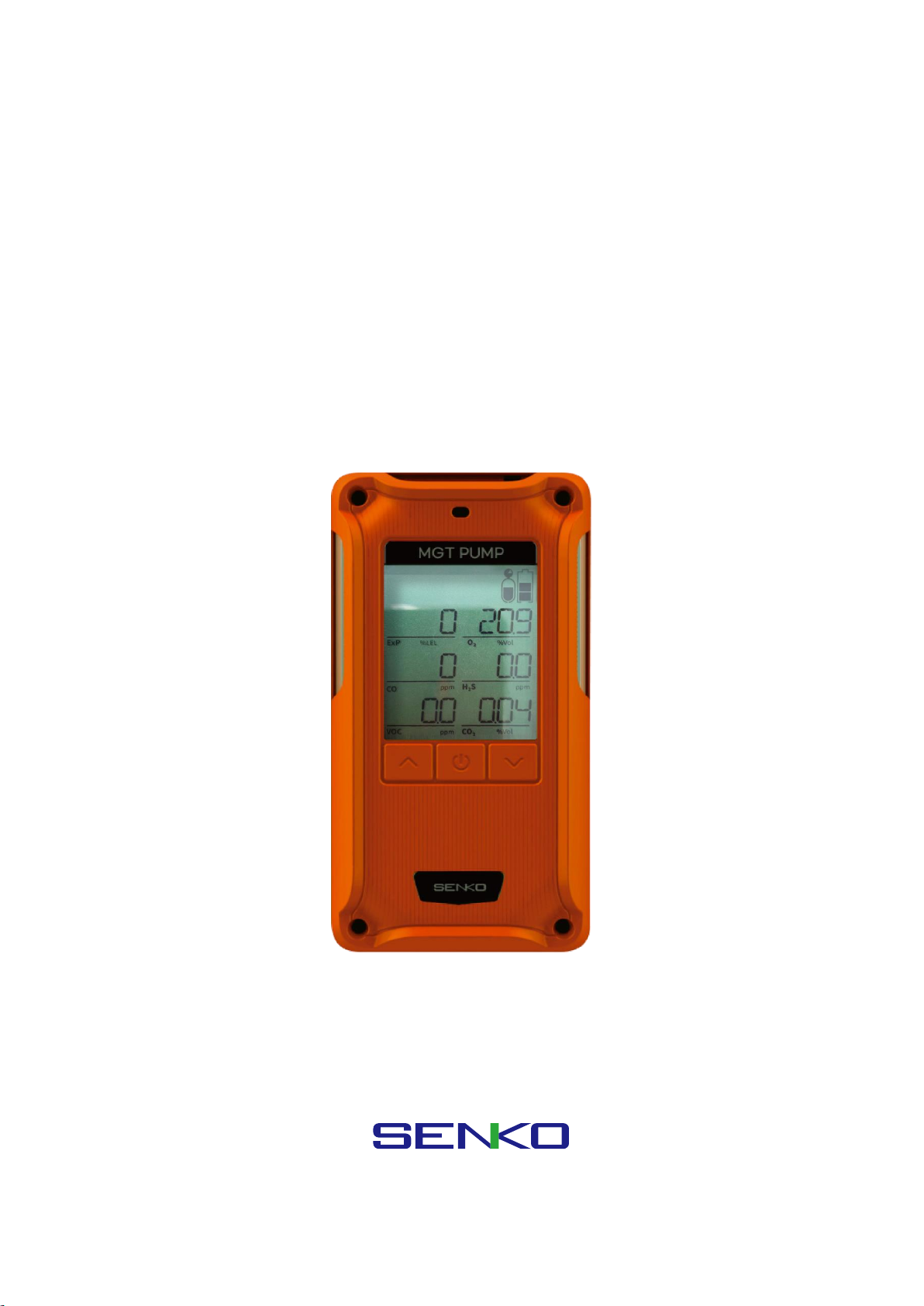
SP-MGTP
(Portable Multi Gas Detector with Pump)
www.senko-detection.com
USER MANUAL

Product Overview
SP-MGTP is a portable multi gas detector with a built-in pump which warns of a dangerous gas
environment. The detector indicates the concentration of up to 6 gases including oxygen, carbon monoxide,
hydrogen sulphide, carbon dioxide, and other toxic and combustible gases simultaneously on the LCD
display. It is easy and simple to operate. The device alerts the operators of danger with an audible, visible,
and vibration alarm when the concentration exceeds safe gas levels. The device shows the gas
concentration in real time and identifies the maximum and minimum concentrations. The settings can be
modified through the SENKO IR-LINK (option).
Warning
➢Please do not replace or change any parts. Unauthorised replacement of parts and/or maintenance will
invalidate the warranty.
➢Please remove any debris on the surfaces of the sensor, LED or buzzer / pump hole before use.
➢Test the performance of the gas sensor using bump test and using calibration gas regularly. The gas
should trigger an alarm to be successful.
➢Test whether the LED, alarm and vibration function properly on a regular basis.
➢Using the device in conditions outside the certified temperature, humidity and pressure range may
cause the instrument to malfunction or fail.
➢The sensors inside the device may indicate the gas concentration differently according to the
temperature, pressure and humidity they are in. Please make sure to calibrate the detector in the same
environment in which it will be used.
➢Extreme changes in temperature may cause drastic changes of the gas concentration. (e.g. using the
detector where there is a huge gap between the inside and outside temperature) Please use the device
when the concentration becomes stable.
➢Severe pressure or impact may cause drastic changes of the gas concentration. Therefore, please use
the device when the concentration is stable. Severe pressure or impact may cause also malfunction in
the sensor or the device.
➢The alarms are set according to the international standard and must be changed by an authorized
expert.
➢Charging or replacing the battery must be done in a safe area where there is no risk of explosion or
fire. The use of spare parts not supplied by the manufacturer will invalidate the warranty.
IR communication should only be done in a safe area where there is no risk of explosion or fire.
➢Do not expose the detector to poisons such as alcohol and citrus based products, as poisons may
damage device’s accuracy and response time.
➢If you suspect sensor poisoning, bump test and calibrate the instrument before further use.
➢The detector is designed for use only in potentially explosive atmospheres where oxygen concentrations
do not exceed 20.9% (v/v). Oxygen deficient atmospheres (<10% v/v) may suppress some sensor
outputs.
➢Recharge the battery before it is discharged.
➢Charge the detector in temperature ranged from 0°C to 40°C
➢The efficiency of the rechargeable battery decreases by approximately 20% after two years of normal
use.
➢Do not use any other charging adapter.
➢Do not calibrate the device while or immediately after charging the battery.
➢Do not calibrate if exposed to the condition representative of the IP rating.
➢Do not perform the calibration during the stabilization process after turning on the device.
➢Sudden changes in atmospheric pressure may cause oxygen concentration to vary temporarily.
➢Before daily use, check the pump port is clear of any obstructions, debris, or blockage.
If the pump port is blocked by any pollutants, the measured reading may be measured lower than the
actual concentration.
➢The equipment shall only be carried and must not be laid down unattended
➢If a charge-generating mechanism is present, the exposed metallic part on the enclosure is
capable of storing a level of electrostatic charge that could ignite IIC gases. Therefore, the
user / installer shall implement precautions, for example, those listed above, to prevent the
build-up of electrostatic charge. This is particularly important if the equipment is being used
in a Zone 0 environment.
➢The equipment shall only be charged while in the non-hazardous area, using a charger
specifically supplied for use with the unit (for example part number ICP12-060-1200D,
manufactured by Shenzhen Shi Ying Yuan Electronics Co, LTD), approved as SELV or Class 2
equipment against IEC 60950, IEC 61010-1 or an equivalent IEC standard. The maximum
voltage and current from the charger shall not exceed 6.3 Vdc plus tolerances and 1.2 A
respectively, and shall be further limited by the charging system to Um = 6.3 Vdc. The ambient
temperature during charging shall be in the range 0 °C to 45 °C.
➢The battery and sensors should only be replaced by SENKO authorized service providers in a safe zone,
free of hazardous gases
Caution
➢Please read the manual carefully.
➢The device is not a gas analyzer, but a gas detector designed to detect the presence of a gas.
➢If the instrument fails to pass calibration, stop using and consult the manufacturer.
➢Test the device every 30 days under the atmospheric environment of clean air without gases.
➢To clean the exterior of the device use only a soft cloth and do not use chemical detergents.
Reference
➢For flammable gas equipment installation, operation and maintenance information, please refer IEC
60079-29-2
➢Conversion for %LEL and %vol follows the ANSI/NFPA 497 standard.

Contents
1. Product Overview ..............................................................................................................................................................5
2 Activation...............................................................................................................................................................................6
2.1. Switch On............................................................................................................................................................................... 6
2.2. Switch Off .............................................................................................................................................................................. 6
3. Pump .......................................................................................................................................................................................6
3.1. Pump Test ................................................................................................................................................................................... 7
3.2 Filter Replacement ................................................................................................................................................................... 7
3.3 Regulator ...................................................................................................................................................................................... 7
4. Display ....................................................................................................................................................................................7
4.1. Measuring Mode ................................................................................................................................................................ 7
4.2. Display Mode ....................................................................................................................................................................... 8
4.2.1 Display Mode in Detail ...................................................................................................................................... 9
4.3. Alarm Display .....................................................................................................................................................................11
4.3. Battery Display...................................................................................................................................................................13
5. Setting and Operation ................................................................................................................................................. 13
5.1. Alarm Menu ........................................................................................................................................................................14
5.2. Calibration Menu..............................................................................................................................................................15
5.2.1. Span Calibration Environment............................................................................................................................15
5.2.2. Zero Calibration (Fresh Air Calibration) .........................................................................................................16
5.2.3. Span Calibration (Standard Gas Calibration) ...............................................................................................16
5.3. Test (Inspection) Menu ..................................................................................................................................................17
5.4. Set Menu..............................................................................................................................................................................18
6. Log......................................................................................................................................................................................... 19
7. Specification...................................................................................................................................................................... 19
7.1. Operating condition.............................................................................................................................................................19
7.2. Storage condition..................................................................................................................................................................20
7.3. Certification..............................................................................................................................................................................20
8. Failure / Escape................................................................................................................................................................ 22
9. Trouble-shooting............................................................................................................................................................. 23
10. Maintenance & Replacement...................................................................................................................................... 23
10.1. Charging..................................................................................................................................................................................23
10.2. Gas Cylinder ..........................................................................................................................................................................24
10.3. Battery......................................................................................................................................................................................24
10.4. Pump.........................................................................................................................................................................................24
10.5. Filter ..........................................................................................................................................................................................24

1. Product Overview
LCD display symbols
High Alarm
Fresh Air Calibration
Low Alarm
Device Stabilization &
Configuration View &
Calibration Succeeded
Alarm Condition
Standard Gas Calibration
STEL Alarm
Remaining Battery
TWA Alarm
2 Activation
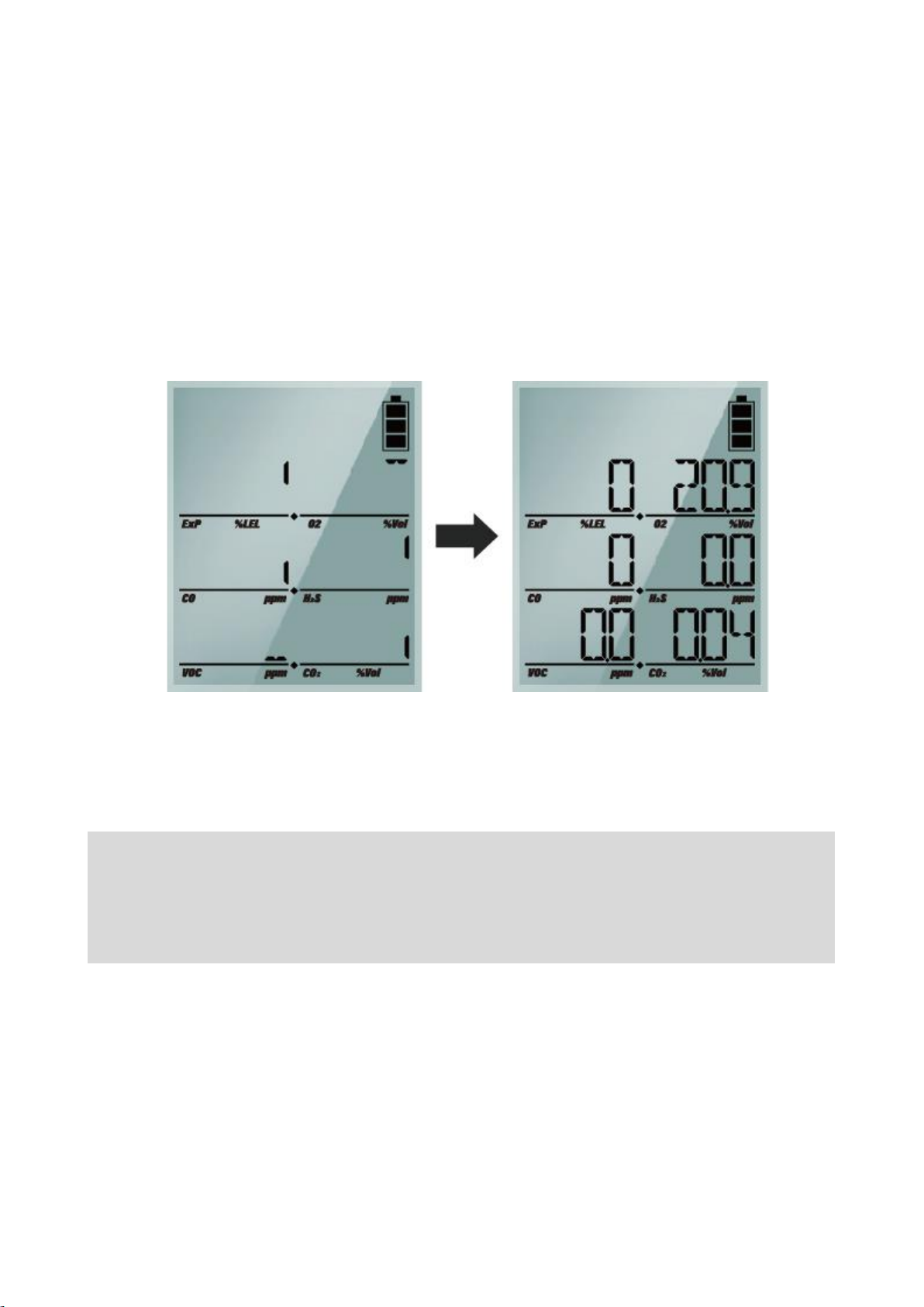
2.1. Switch On
Press the power button for 2 seconds and SYS boot is displayed. Once the device turns on, the version
and LCD are displayed. After 10 seconds of system test, the warmup will begin.
If errors occur during system test, the device will indicate error code. (Regarding error code, please refer
to the Chapter 8(Failure and Escape).
The exact warmup time differs depending on which sensor types are fitted. After completing the warmup,
the device goes into the measurment mode.
2.2. Switch Off
To switch off, press and hold down the enter button for three seconds. The display counts down three
seconds with the “SYS OFF” message.
(The device will not be switched off only unless you keep pressing the button for longer than three
seconds.)
<Caution> To check the gas response performance of the sensor, it is recommended to do a bump test
with gas concentration higher than the alarm set point. It is recommended to do a bump test before
each use of the device. Users are required to check if the device is working properly and ensure the
pump port is clear of any obstructions, debris, or blockage.
Initial Setting Mode
Gas Measuring Mode
3. Pump
3.1. Pump Test
When you change the gas tube or reconnect to the detector, test the sampling system by blocking the
end of the tube. When the flow is blocked, the device will alarm every second. If no alarm activates this
indicates a leak in the system or a failure of the pump.
3.2 Filter Replacement
The gas inlet is protected by the particulate filter and membrane filter. When the filter is blocked, the
sampling system will be unable to work and the warning alarm will be activated sounding every second.
Visually inspect the filter to ensure the filter is free of debris or obstructions. Discolouration of the filter is
the best indicator that the filter needs replacing. If the filter needs to be replaced, loosen the two screws
and replace with new filters. After replacing with new filter, reassemble the screws and continue to use it.
3.3 Regulator
The detector has an internal pump drawing the gas, so when performing a calibration or bump test, a
demand flow regulator should be used on the gas cylinder.
4. Display
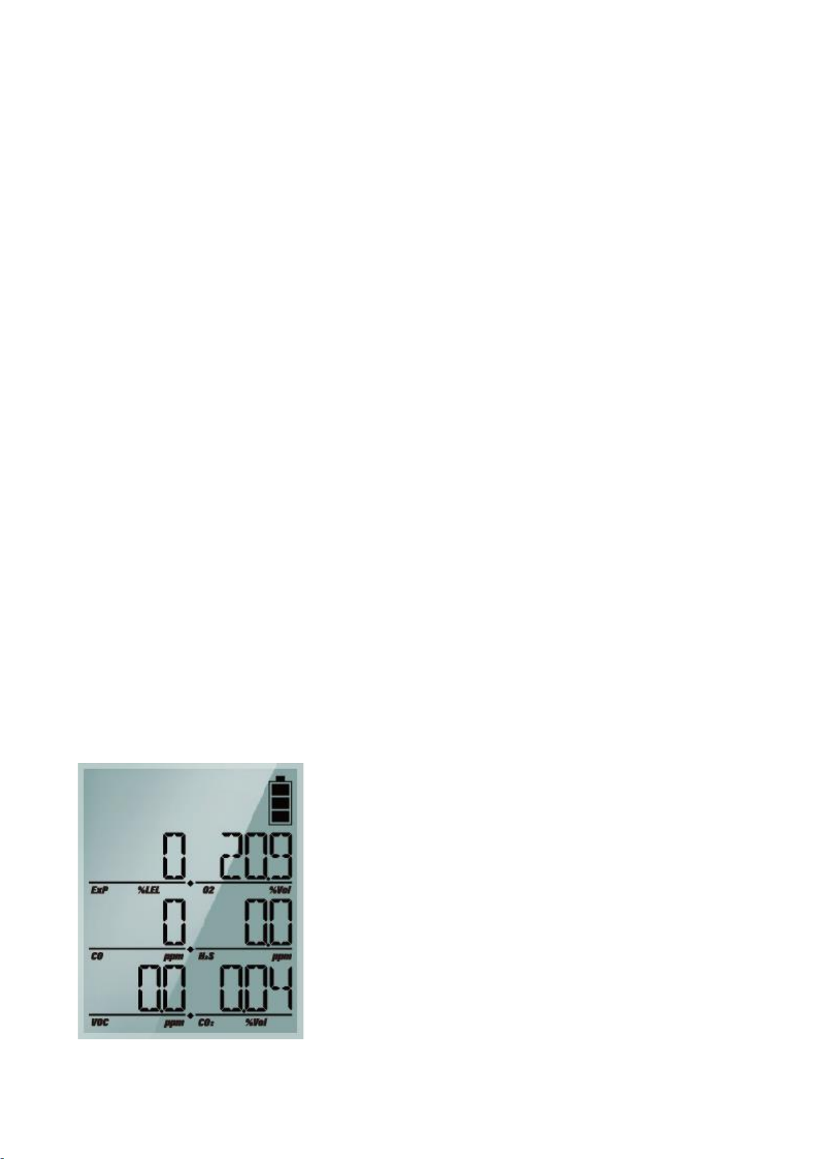
4.1. Measuring Mode
After stabilization the device goes into the normal measuring mode. The gas concentration and the battery
power level are displayed on the LCD display. Oxygen is displayed in %vol, combustible gases in %LEL and
H2S, CO in PPM (parts per million). When the gas concentration levels change, the value is displayed in
real time, and when the levels exceed the threshold for either LOW alarm or HIGH alarm (or TWA/STEL),
the display icons of
LOW
,
HIGH
,
TWA
or
STEL
flash regularly and the audible, visual and vibration alarms
activate.
When the concentration detected by the device returns below the alarm threshold, the alarms stop,
however the alarm icon continues to indicate that an alarm has occurred until the Enter button is pressed
to accept it.
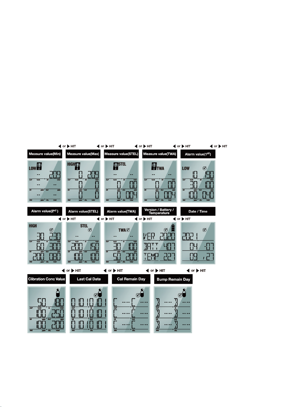
4.2. Display Mode
Pressing the △ or ▽ button steps the display through fourteen different display modes as shown above.
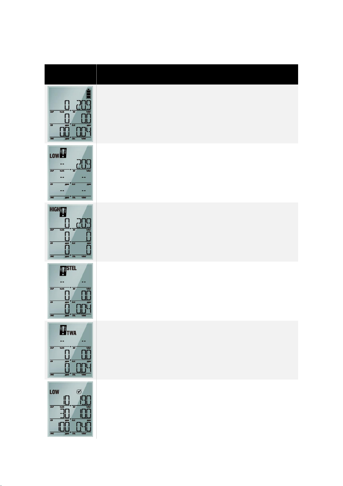
4.2.1 Display Mode in Detail
LCD Display
Images
Description in Detail
➢Measuring Mode (Basic Display)
➢Display the current gas levels of the atmosphere and the battery
power level
➢A low gas alarm has been triggered.
*In an ambient air, the Oxygen level normally indicates 20.9%vol.
➢A high gas alarm has been triggered.
*In an ambient air, the Oxygen level normally indicates 20.9%vol.
➢A STEL (Short Term Exposure Limit) gas alarm has been triggered
indicating the 15 minutes average exposure has been exceeded
➢A TWA (Time weighted average) gas alarm has been triggered
indicating the 8 hours average exposure has been exceeded
➢Display the preset low alarm levels.
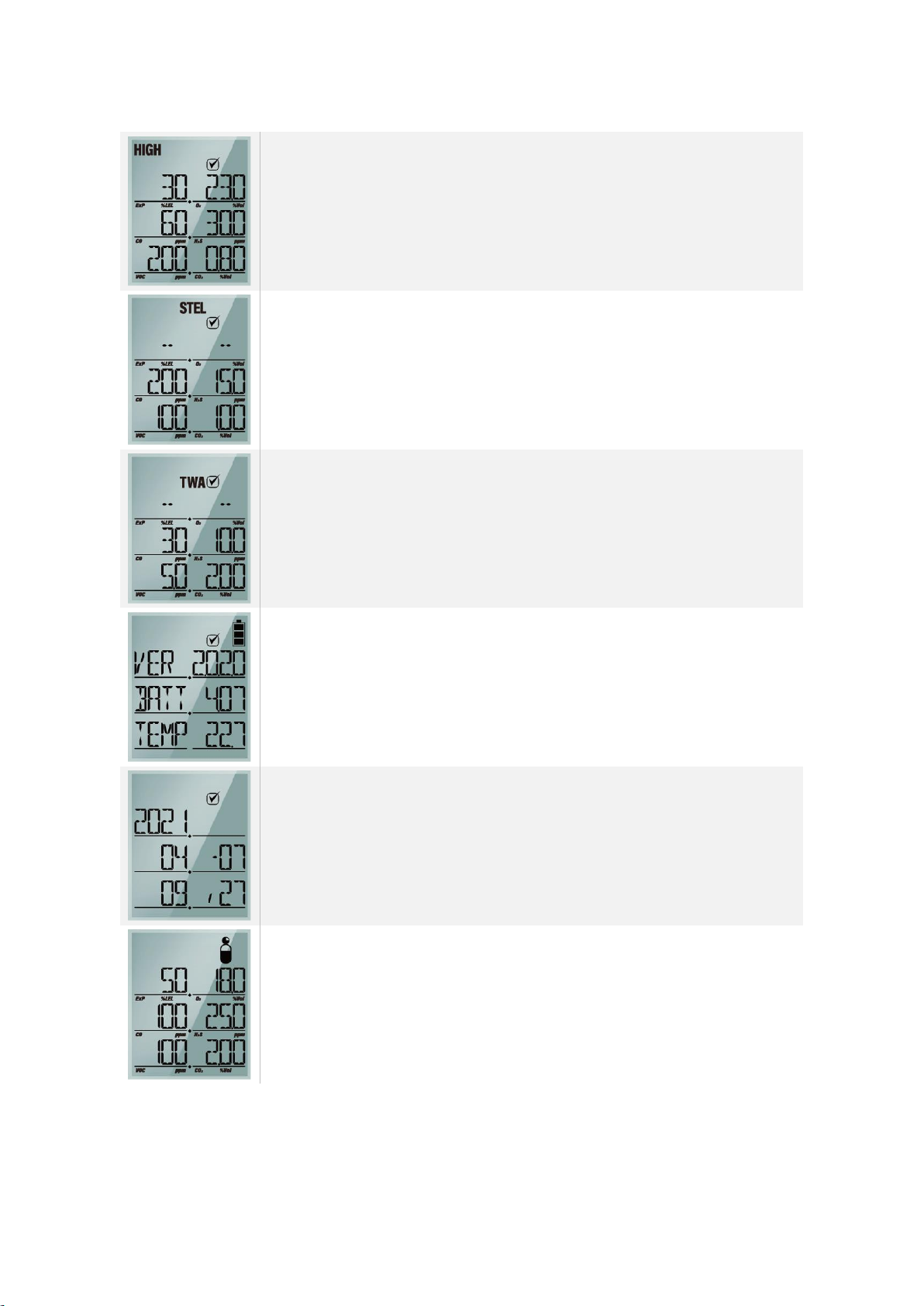
➢Display the preset high alarm levels.
➢Display the preset STEL levels.
➢Display the preset TWA levels.
➢Firmware Version, Current battery voltage, Current
temperature(Celsius)
➢Date / Time
➢Calibration Concentration Value
Altri manuali per SP-MGTP
1
Indice
Altri manuali SENKO Rilevatore di gas

SENKO
SENKO MGT Manuale utente

SENKO
SENKO iGas Detector CO2 Manuale utente

SENKO
SENKO SI-H100 Manuale utente

SENKO
SENKO SI-100 Manuale utente

SENKO
SENKO SGT-P Manuale utente

SENKO
SENKO SI-300 Manuale utente

SENKO
SENKO SP-MGTP Manuale utente

SENKO
SENKO SGT Manuale utente

SENKO
SENKO SI-100C Manuale utente

SENKO
SENKO RAITEC SI-100D Manuale utente


