
SGC Smartuner SG-211 Manuale utente
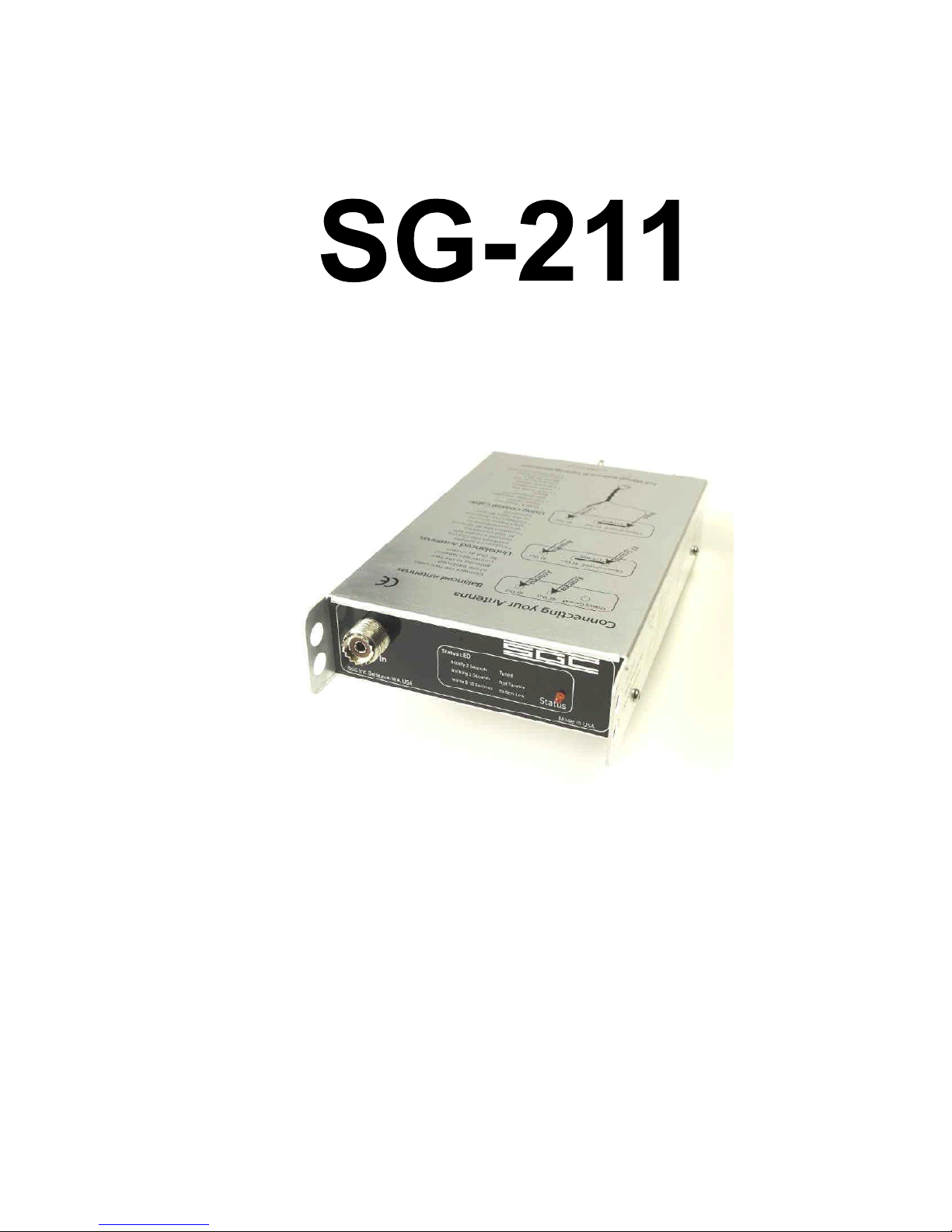
Catalog Number 54-26
April 2004
The Zero Power Smartuner
Thank you for buying your new SG-
211 Antenna Coupler. The SG-211
incorporates the very latest
American-made technology as well as
our experience in having delivered
more than 100,000 Smartuners since
1985. It is a state-of-the-art tuner
providing a new and unique level of
usefulness.
The concept of the SG-211 is quite
different from the rest of our line of
Smartuners. It is a unique departure
designed to provide flexible matching
capabilities in a portable environment
where power is at a premium. The
ease of installation and flexible
operation make this an ideal choice
when power is limited. We know that
the simplicity, reliability, and
flexibility of the SG-211 will enhance
your HF operation for years to come.
SGC continues to focus on providing
the most useful products and services
for our customers around the world.
Please feel free to call to discuss your
antenna system requirements at any
time. We look forward to making your
HF experience the very best.
Pamela Goral
President
Mailing: PO Box 3526, Bellevue, WA. 98009
Shipping: 13737 SE 26th St. Bellevue, WA. 98005
Toll Free: 800-259-7331 * Phone: 425-746-6310 * Fax: 425-746-6384
Pierre Goral
Founder
1936-2004

SG-211 User’s Manual
© 2004 SGC Inc. Page 1
Warnings
IMPORTANT NOTE: A random antenna wire will
radiate RF. Not only is this an RF Hazard within the
station, but it can cause local interference both within the
station and in the vicinity depending on your power level.
CAUTION: Unbalanced antennas are radiating from the
line as soon as they leave the SG-211. Minimize the
amount of wire inside the radio room to prevent
interference with electronic equipment. Minimizing
power will also minimize interference caused by this kind
of antenna.

SG-211 User’s Manual
© 2004 SGC Inc. Page 2
Quick Start/Reference

SG-211 User’s Manual
© 2004 SGC Inc. Page 3
Table of Contents
1INTRODUCTION ................................................ 5
1.1 SPECIFICATIONS............................................. 5
1.2 MECHANICAL DESIGN ................................... 7
2SG-211 SETUP ..................................................... 8
2.1 CONNECTIONS TO THE SG-211 ...................... 8
2.1.1 RF Input from your transceiver................ 8
2.1.2 Antenna and RF Ground Connections ..... 9
2.2 BATTERY REPLACEMENT............................. 11
3ANTENNAS AND THE SG-211 ....................... 13
3.1 OPTIMUM COUPLING ................................... 13
3.2 CONNECTING ANTENNAS............................. 13
3.3 BALANCED VS. UNBALANCED ANTENNAS... 15
3.4 ANTENNA RECOMMENDATIONS................... 16
3.4.1 Dipoles ................................................... 16
3.4.2 The Inverted V Antenna.......................... 17
3.4.3 Dipoles with Matching Lines ................. 17
3.4.4 Long Wires & Inverted Ls ...................... 18
3.4.5 Vertical Antennas................................... 20
3.4.6 Loops...................................................... 23
3.4.7 Portable Antennas.................................. 24
3.4.8 Beams..................................................... 27
3.5 TIPS & TRICKS............................................. 27
3.6 REFERENCES ON ANTENNAS ........................ 29
3.6.1 From SGC .............................................. 29
3.6.2 Books...................................................... 29
3.7 THE GOLDEN RULES OF HF INSTALLATION.30
3.8 DO-IT-YOURSELF LIGHT BULB TEST ........... 31
4THEORY OF OPERATION ............................. 35
4.1 NO EXTERNAL POWER REQUIRED ............... 35

SG-211 User’s Manual
© 2004 SGC Inc. Page 4
4.2 THE MATCHING NETWORK.......................... 36
4.3 THE SENSOR ................................................ 37
4.4 THE RELAY DRIVER MATRIX ...................... 38
4.5 MICROPROCESSOR ....................................... 39
5COMPONENT LOCATION ............................. 41
6SCHEMATICS ................................................... 43
7STANDARD WARRANTY ............................... 48
SG-211 User’s Manual
© 2004 SGC Inc. Page 5
1Introduction
1.1 Specifications
The SG-211 is a revolution. You’ve never seen a coupler
so light weight or so flexible. Never has there been one so
easy to carry and use. And NEVER have you seen one
that will tune for 5 years on a single set of AA cells!

SG-211 User’s Manual
© 2004 SGC Inc. Page 6
HF Frequency Range: 1.8-60 MHz
Power Input Range:
(approximate)
60 watts (PEP) 30 watts key-down
30 watts (PEP) with short antennas below
3.5 Mhz
20 watts data continuous operation
Minimum Sensitivity Approximately 1 watt
Memory bins: 256
Input Impedance Range: .3-6000 ohms
VSWR: Typically less than 2:1
DC Input Requirement: None (internal battery)
Input Current: Zero
Random set time: Average 4 seconds
Recurrent set time: Typically less than 500 milliseconds
Antenna Length: 25 foot wire or whip from 1.8-60 Mhz
8 foot wire or whip from 3.5-60 Mhz
Installation: Any position
Operating Temperature: -30° to +60°C
Size: 8.66 inches X 4.69 inches X 1.55 inches
Weight: 1 lb
Case Construction: Irridited Aluminum
Antenna types: 1. Whip
2. Backstay (marine, sail)
3. Dipole centerfed
4. Dipole with feedline
5. Loop (small) 2x2 multi turn
6. Loop (large) 10 ft. and up single turn
7. Longwire
8. Ladder feed
9. Coaxial Fed Antennas
Power Source 4 AA Batteries lasting 5 years
Front Panel Connections SO-239 RF Input Connector
Rear Panel Connections Balanced and Unbalanced Wing Nuts
Indicators 1 Red LED on Front Panel:
Steady for 2 seconds for tuned
Blinking for 2 seconds for not tunable
Morse B for 10 seconds for battery low

SG-211 User’s Manual
© 2004 SGC Inc. Page 7
1.2 Mechanical Design
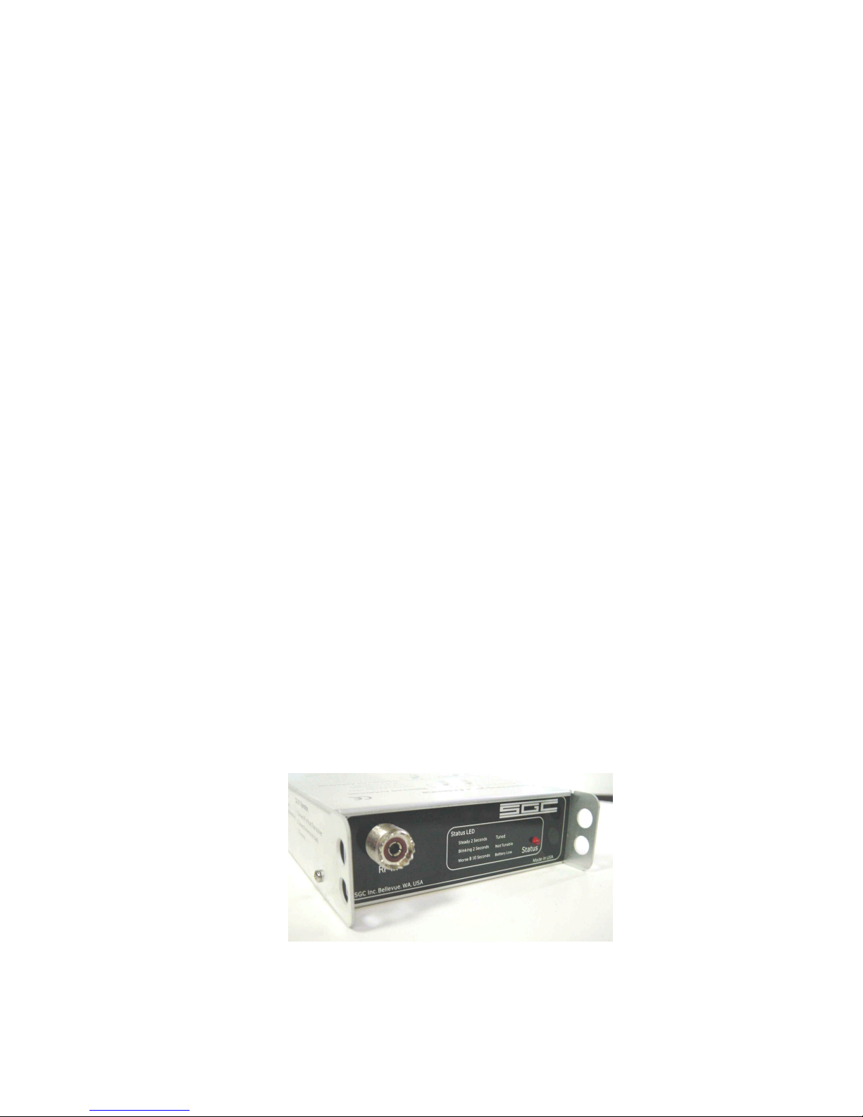
The SG-211 is in an Irridited Aluminum case.
The RF input connector is an SO-239 on the
front of the case. RF Output is from balanced
and unbalanced connectors on the back. Internal
construction makes the SG-211 suitable for
portable or fixed location use. Corrosion-
resistant hardware and passive alloys are used
throughout.
SG-211 User’s Manual
© 2004 SGC Inc. Page 8
2SG-211 Setup
Setup on the SG-211 is so easy there is almost nothing to
do. It comes with AA batteries already installed. All you
need to do is connect the coax from your transceiver,
attach your antenna to the terminals on the back, and the
SG-211 is ready to go.
2.1 Connections to the SG-211
2.1.1 RF Input from your transceiver
RF input to the SG-211 is through a standard SO-239
connector on the front. Choose good quality coaxial cable
with a PL-259 connector. You may want to add a
Power/SWR meter between the transceiver and the SG-
211 to monitor conditions. We recommend that you select
one that measures Forward and Reverse power as well as
SWR. This will provide more useful information about
conditions on the line.
Indice
Altri manuali SGC Sintonizzatore


