
SHORE TEL Mobility Router 4000 Manuale

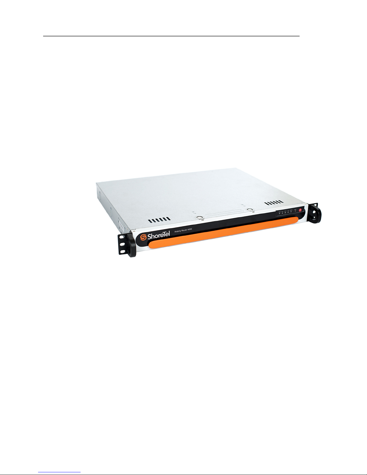
ShoreTel Mobility Router 4000 Series
Hardware Installation Guide

Document and Software Copyrights
Copyright © 1998-2012 by ShoreTel Inc., Sunnyvale, California, USA. All rights reserved.
Printed in the United States of America. Contents of this publication may not be reproduced or transmitted in any
form or by any means, electronic or mechanical, for any purpose, without prior written authorization of ShoreTel,
Inc. ShoreTel, Inc. reserves the right to make changes without notice to the specifications and materials contained
herein and shall not be responsible for any damage (including consequential) caused by reliance on the materials
presented, including, but not limited to typographical, arithmetic or listing errors
Trademarks
ShoreTel, ShoreTel (and logo), ControlPoint, Brilliantly Simple, Brilliantly Simple Communication, ShoreCare,
ShoreGear, ShorePhone, and ShoreWare are registered trademarks of ShoreTel, Inc. in the United States and/or
other countries. The ShoreTel logo is a trademark of ShoreTel, Inc. in the United States and/or other countries..
All other copyrights and trademarks herein are the property of their respective owners.
Version Information
ShoreTel Mobility Router 4000 Series Hardware Installation
Date: April 23, 2012
Part Number: 850-1321-02
Company Information
www.shoretel.com
ShoreTel, Inc.
960 Stewart Drive
Sunnyvale, California 94085 USA
US / Canada
+1 800 742-2348
+1 (408) 962-4550
United Kingdom
+44 808 13 49920
+44 (0) 1628 826399
Europe
+00 800 4083 3133
Australia / New Zealand
+61 800 258 533
+61 2 9959 8080
For product support, contact ShoreTel Technical Support at http://support.shoretel.com.
ShoreTel Mobility Router 4000 Series Hardware Installation Guide 1
ShoreTel Mobility Router 4000 Installation
Overview 1
1
ShoreTel Mobility Router 4000
Installation
1.1 Overview
This Hardware Installation Guide provides the following instructions for installing and
initially configuring the ShoreTel Mobility Router 4000.
This document is intended for network administrators who install and manage network
equipment, and contains the following sections:
“Specifications” on page 2
“Unpacking a Mobility Router” on page 4
“Installation Requirements and Recommendations” on page 5
“Installing the Mobility Router” on page 6
“Connecting to the Network” on page 7
“Connecting to the Console Port” on page 8
“Connecting Power” on page 9
“Using the Initial Configuration Wizard” on page 10
ShoreTel Mobility Router 4000 Installation
Specifications
1
2 ShoreTel Mobility Router 4000 Series Hardware Installation Guide
1.2 Specifications
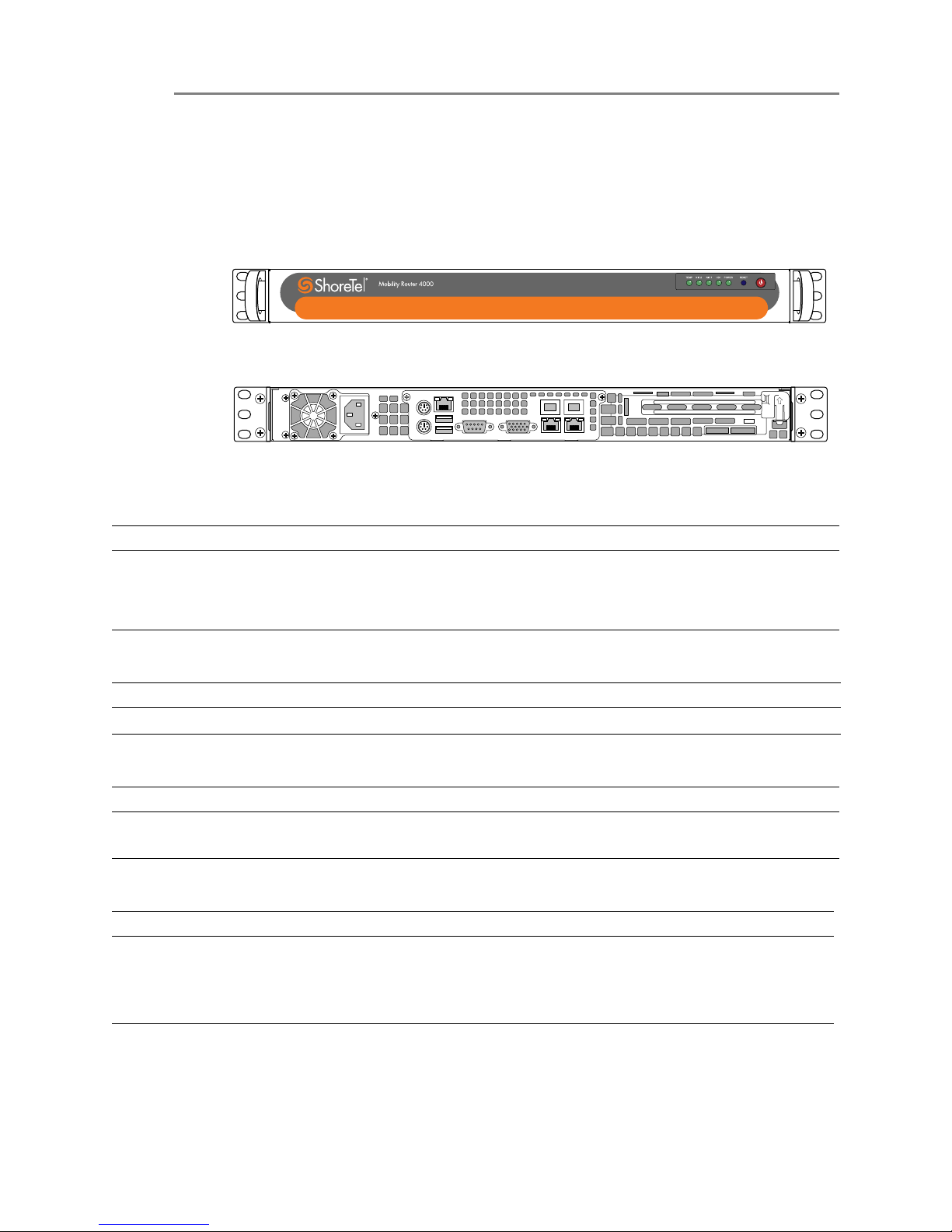
The Mobility Router is one rack unit (RU) high and installed in a standard 19-inch
(48.26-cm) rack.
Figure 1-1. Front View of RoamAnywhere Mobility Router 4000 Series
Figure 1-2. Rear View of RoamAnywhere Mobility Router 4000 Series
Table 1-1 Mobility Router Connection Specifications
Table 1-2 Mobility Router Power Specifications
Table 1-3 Mobility Router Physical Specifications
Table 1-4 Mobility Router Operating Environment
Model Port Connection
ShoreTel Mobility Router 4000 Series Ethernet
Console
1 ea. ETH0
1 ea. ETH1
Serial
Model Power Supply
ShoreTel Mobility Router 4000 Series 100-240 VAC (auto-range), 200 W, 3A, 50-60 Hz
Model Dimensions (WxHxD)Weight
ShoreTel Mobility Router 4000 Series 16.8 x 1.7 x 14 inches
(427 x 43 x 356 mm)
17.7 lb (7.7 kg)
Model Temperature Humidity
ShoreTel Mobility Router 4000 Series Operating: 10º to 35º C
(50º to 95º F)
Non-operating: -40º to 70º C
(-40º to 158º F)
Operating: 8% to 90%
(non-condensing)
Non-operating: 5 to 95%
(non-condensing)

ShoreTel Mobility Router 4000 Series Hardware Installation Guide 3
ShoreTel Mobility Router 4000 Installation
Specifications 1
Table 1-5 Status LEDs
Regulatory compliance:
Electromagnetic Emissions: FCC Class A, EN 55022 Class A, EN 61000-3-2/-3-3, CISPR
22 Class A
Electromagnetic Immunity: EN 55024/CISPR 24, (EN 61000-4-2, EN 61000-4-3, EN
61000-4-4, EN 61000-4-5, EN 61000-4-6, EN 61000-4-8, EN 61000-4-11)
Safety: CSA/EN/IEC/UL 60950-1 Compliant, UL or CSA Listed (USA and Canada), CE
Marking (Europe)
LED Appearance Meaning
Power On continuously Indicates that power is supplied to power supply unit.
Hard drive activity Blinking green Indicates hard drive activity.
Blinking red Indicates that the hard drive is rebuilding.
Solid red Indicates that the hard drive has failed.
LAN activity (eth1) — This LED is not currently operational.
LAN activity (eth0) Blinking Indicates network activity on the eth0 port.
Overheating/fan failure Blinking Indicates fan failure.
On continuously Indicates that the Mobility Router is overheated.

ShoreTel Mobility Router 4000 Installation
Unpacking a Mobility Router
1
4 ShoreTel Mobility Router 4000 Series Hardware Installation Guide
1.3 Unpacking a Mobility Router
The carton for a Mobility Router contains the following:
One Mobility Router
End-user license agreement (EULA)
One power cord
One serial cable for serial console connection
One straight-through Ethernet cable
A copy of this document
Before starting the installation:
1Open the carton and remove the contents.
2If any contents are missing or damaged, contact ShoreTel Technical Support at
+1.408.331.3300 or http://support.shoretel.com.
3Keep the packing materials and save the carton.

ShoreTel Mobility Router 4000 Series Hardware Installation Guide 5
ShoreTel Mobility Router 4000 Installation
Installation Requirements and Recommendations 1
1.4 Installation Requirements and
Recommendations
Before installing a Mobility Router, follow these requirements and recommendations.
1.4.1 Installation Location Guidelines
The Mobility Router should be installed in an environment sufficient for normal operation of
network appliances (50-95°F). Make sure that the area allows for enough ventilation after the
Mobility Router is installed. The appliance should be installed in an area that does not exceed
the following humidity range: 8-90% non-condensing.
1.4.2 Rack Requirements
The Mobility Router must be installed in a standard 19-inch rack. Make sure that the Mobility
Router is installed in the rack so that the Mobility Router is level in the rack and is fastened
by screws on both sides. Refer to “Installing the Mobility Router” on page 6 for installation
instructions.
1.4.3 Required Equipment for Installation
The following equipment is required for rack installation (and depends on the type of rack):
Mounting screws to rack mount the Mobility Router (not provided)
Screwdriver (not provided)
1.4.4 Uninterruptible Power Supply
We recommend installing the Mobility Router in an existing Uninterruptible Power Supply
(UPS) infrastructure.
ShoreTel Mobility Router 4000 Installation
Installing the Mobility Router
1
6 ShoreTel Mobility Router 4000 Series Hardware Installation Guide
1.5 Installing the Mobility Router
Required Tools:
4 each “cage” type mounting nuts (not included)
4 each Pan Head screws, typically 10-32 thread size (not included)
To connect the Mobility Router to the rack:
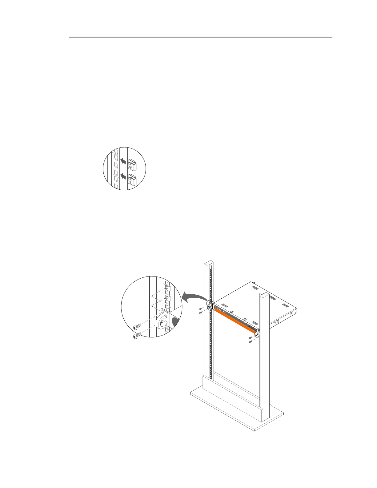
1Snap the mounting nuts into the rack at the desired mounting point.
Figure 1-3. Insert Mounting Nuts into Rack
2Lift the Mobility Router to the desired rack position.
3Install each Pan Head screw through the Mobility Router’s mounting ears into the
mounting nuts.
Figure 1-4. Fastening the Mobility Router to the Rack
4Tighten to 30 inch-lbs. Do not over-tighten.
tbd screws being inserted (with arrows) into ears
RESET
TEMP NIC2 NIC1HD1POWER
ShoreTel Mobility Router 4000 Series Hardware Installation Guide 7
ShoreTel Mobility Router 4000 Installation
Connecting to the Network 1
1.6 Connecting to the Network
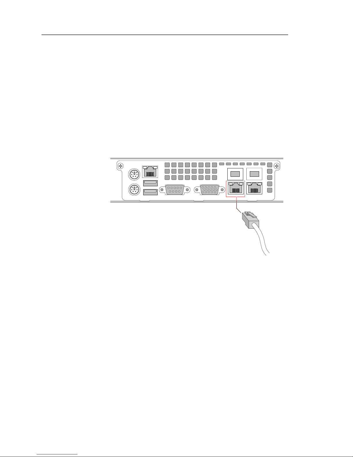
Connect the Mobility Router to a network device, such as a switch, using the straight-through
Ethernet cable provided with the Mobility Router.
To connect the Mobility Router to the network:
1Insert one end of the Ethernet cable to the network device.
2Insert the other end of the Ethernet cable to the left Ethernet port (ETH0) on the rear of
the Mobility Router.
NOTE If using the Secure Remote Voice feature, connect the second Ethernet port
(ETH1) to the external network.
Figure 1-5. Connecting the Ethernet Cable to the Mobility Router
ShoreTel Mobility Router 4000 Installation
Connecting to the Console Port
1
8 ShoreTel Mobility Router 4000 Series Hardware Installation Guide
1.7 Connecting to the Console Port
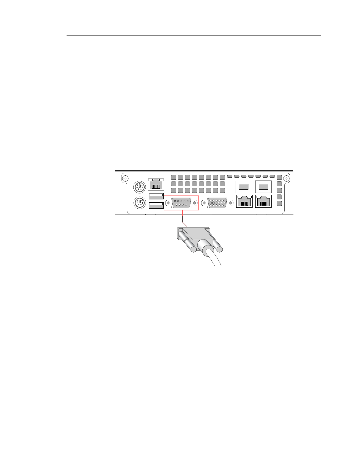
The Mobility Router uses a serial console port to provide a direct connection to the
command-line interface (CLI) Wizard for initial configuration the Mobility Router. After
completing the initial configuration, access to the console port is no longer necessary.
To initially configure the Mobility Router, connect the management PC or laptop to the serial
console port of the Mobility Router. If there is no serial port, use a 9-pin serial to USB adapter
to connect to the serial cable.
To connect the PC or laptop to the serial console port:
1Insert one end of the serial cable into the PC or laptop serial port.
2Insert the other end of the cable into the serial console port of the Mobility Router.
Figure 1-6. Connecting to the Serial Console Port
3On the PC or laptop, start terminal emulation software (such as Microsoft
HyperTerminal) and select the appropriate COM port.
4Configure the port using the following settings:
Baud rate: 9600 bps
Data bits: 8
Parity: None
Stop bits: 1
Flow control: None
Questo manuale è adatto per i seguenti modelli
1
Indice
Altri manuali SHORE TEL Router di rete


Manuali Router di rete popolari di altre marche


NETGEAR
NETGEAR FS526T - Switch Manuale utente

Korenix
Korenix JetNet 5710G Series Manuale utente

Automated Logic
Automated Logic ZN551 Manuale del proprietario

Cisco
Cisco ASR 1000 Series Manuale dell'operatore

EnGenius
EnGenius ESR-9710 Manuale utente

Cisco
Cisco 805 Series Istruzioni operative e di sicurezza