SICK WTV4-3 V-optic Manuale utente

OPERATING I N S T R U C T I O N
en / de / fr / it / pt / es / zh / ru
SICK AG, Erwin-Sick-Strasse 1, D-79183 Waldkirch
8011167.126R
2006/42/EG
NO
SAFETY

Photoelectric proximity sensor
Operating instructions
1 Safety notes
■Read the operating instructions before commissioning.
■Connection, mounting, and setting may only be performed by trained specialists.
■Not a safety component in accordance with the EU Machinery Directive.
■UL: Only for use in applications in accordance with NFPA 79. These devices shall
be protected by a 1 A fuse suitable for 30 V DC. Adapters listed by UL with connec‐
tion cables are available. Enclosure type 1.
■When commissioning, protect the device from moisture and contamination.
■These operating instructions contain information required during the life cycle of
the sensor.
2 Correct use
The WTV4-3 is an opto-electronic photoelectric proximity sensor (referred to as "sensor"
in the following) for the optical, non-contact detection of objects, animals, and persons.
If the product is used for any other purpose or modified in any way, any warranty claim
against SICK AG shall become void.
Photoelectric proximity sensor with foreground suppression.
Image: A
3 Commissioning
1 Mount the sensor using a suitable mounting bracket (see the SICK range of acces‐
sories).
Note the sensor's maximum permissible tightening torque of 0.8 Nm.
Note the preferred direction of the object relative to the sensor [see A].
2 The sensors must be connected in a voltage-free state (VS = 0 V). The information
in the graphics [B] must be observed, depending on the type of connection:
1
Image: D
Specifications see page 48.
8011167.126R | SICK
Subject to change without notice

– Male connector connection: pin assignment
– Cable: core color
Image: B
Only apply voltage/switch on the power supply (VS > 0 V) once all electrical connec‐
tions have been completed. The green LED indicator lights up on the sensor.
Explanations of the connection diagram (Graphic B):
Switching outputs Q and /Q (according to Graphic B):
WTV4-3Exxxx and WTV4-3Fxxxx
D: dark-switching, output (Q) switches off when an object is present in the sensing
range.
WTV4-3Px1xx and WTV4-3Nx1xx
L: light switching, output (Q) switches when an object is present in the sensing ran‐
ge.
WTV4-3P1141 and WTV4-3N1141
WTV4-3Px241 and WTV4-3Nx241
ANT: complementary outputs Q and Q/
3Sensor with potentiometer:
The sensing range is adjusted with the potentiometer (type: 5-Gang). Clockwise ro‐
tation: sensing range increased; counterclockwise rotation: sensing range reduced.
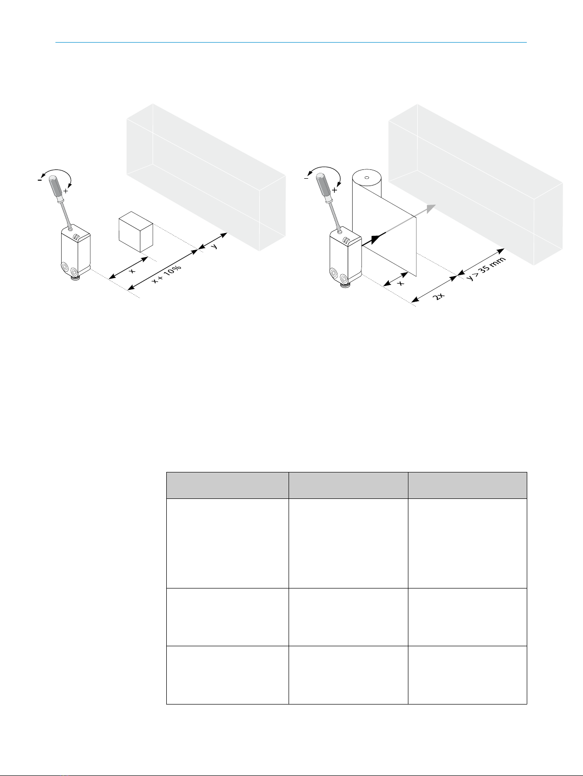
Standard detection of non-transparent objects:
Ensure that the transition range between the sensing range (x) and the background
(y) is > 2.5 mm (cf. E). Sensor has no significant S/W shift.
Detection of transparent objects:
K = tilt angle
Optimum detection of transparent objects aligned parallel to the sensor, at a dis‐
tance of 15 mm to 25 mm. It is recommended to set the scanning range to twice
the object distance (cf. F & G). Recommended transition range between the scan‐
ning range (x) and the background (y) is at least 35 mm (cf. G). The greater the dis‐
tance between the scanning range and the background, the better the detection
reliability.
Standard setting for non-transparent objects:
Position the object and direct the light spot onto it. Red emitted light spot can be
detected on the object. Turn the adjustment to the minimum scanning range. Then
increase the scanning range until the yellow LED indicator lights up. Recommen‐
ded: If high contrast or poorly remitting objects are detected, increase the scanning
range by adding a safety supplement of 10% of the scanning range (cf. F).
Standard setting for transparent objects:
Keep diffuse bright object (e.g. cardboard insert for packaging) in the beam path at
twice the sensing range. Set sensor according to "Setting for non-transparent ob‐
jects". Keep transparent object in the beam path. The yellow indicator LED lights
up. If the beam path fails to behave in accordance with Graphic C/D and G, check
application conditions. See section Fault diagnosis.
The sensor is adjusted and ready for operation. Refer to Graphics C/D and G to
check the function. If the switching output fails to behave in accordance with Gra‐
phic C/D, check application conditions. See section Fault diagnosis.
3 COMMISSIONING
28011167.126R | SICK
Subject to change without notice

Image: C
Image: G
5 Fault diagnosis
Table indicates which measures are to be taken if the sensor stops working.
4
3
Image: E
Image: F
8011167.126R | SICK
Subject to change without notice

6 Table Fault diagnosis
LED indicator/fault pattern /
LED indicator/fault pattern
Cause /
Cause
Measures /
Measures
Green LED does not light up /
Green LED does not light up
No voltage or voltage below
the limit values /
No voltage or voltage below
the limit values
Check the power supply,
check all electrical connecti‐
ons (cables and plug connecti‐
ons) /
Check the power supply,
check all electrical connecti‐
ons (cables and plug connecti‐
ons)
Green LED does not light up /
Green LED does not light up
Voltage interruptions /
Voltage interruptions
Ensure there is a stable power
supply without interruptions /
Ensure there is a stable power
supply without interruptions
Green LED does not light up /
Green LED does not light up
Sensor is faulty /
Sensor is faulty
If the power supply is OK, re‐
place the sensor /
If the power supply is OK, re‐
place the sensor
Yellow LED flashes /
Yellow LED flashes
Sensor is still ready for opera‐
tion, but the operating conditi‐
ons are not ideal /
Sensor is still ready for opera‐
tion, but the operating conditi‐
ons are not ideal
Check the operating conditi‐
ons: Fully align the beam of
light (light spot) with the back‐
ground. / Clean the optical
surfaces . / Readjust the sen‐
sitivity (potentiometer) /
Check sensing range and ad‐
just if necessary; see graphic
F. /
Check the operating conditi‐
ons: Fully align the beam of
light (light spot) with the back‐
ground. / Clean the optical
surfaces . / Readjust the sen‐
sitivity (potentiometer) /
Check sensing range and ad‐
just if necessary; see graphic
F.
7 Disassembly and disposal
The sensor must be disposed of according to the applicable country-specific regulati‐
ons. Efforts should be made during the disposal process to recycle the constituent ma‐
terials (particularly precious metals).
8 Maintenance
SICK sensors are maintenance-free.
We recommend doing the following regularly:
•Clean the external lens surfaces
•Check the screw connections and plug-in connections
No modifications may be made to devices.
Subject to change without notice. Specified product properties and technical data are
not written guarantees.
6 TABLE FAULT DIAGNOSIS
48011167.126R | SICK
Subject to change without notice

Reflexions-Lichttaster
Betriebsanleitung
9Sicherheitshinweise
■Vor der Inbetriebnahme die Betriebsanleitung lesen.
■Anschluss, Montage und Einstellung nur durch Fachpersonal.
■Kein Sicherheitsbauteil gemäß EU-Maschinenrichtlinie.
■UL: Nur zur Verwendung in Anwendungen gemäß NFPA 79. Diese Geräte müssen
mit einer für 30V DC geeigneten 1A-Sicherung abgesichert werden. Von UL geliste‐
te Adapter mit Anschlusskabeln sind verfügbar. Enclosure type 1.
■Gerät bei Inbetriebnahme vor Feuchte und Verunreinigung schützen.
■Diese Betriebsanleitung enthält Informationen, die während des Lebenszyklus des
Sensors notwendig sind.
10 Bestimmungsgemäße Verwendung
Die WTV4-3 ist ein optoelektronischer Reflexions-Lichttaster (im Folgenden Sensor ge‐
nannt) und wird zum optischen, berührungslosen Erfassen von Sachen, Tieren und Per‐
sonen eingesetzt. Bei jeder anderen Verwendung und bei Veränderungen am Produkt
verfällt jeglicher Gewährleistungsanspruch gegenüber der SICK AG.
Reflexionslichttaster mit Vordergrundausblendung.
Abb.: A
5
Technische Daten siehe Seite 48.
8011167.126R | SICK
Subject to change without notice

Abb.: D
11 Inbetriebnahme
1 Den Sensor an einen geeigneten Befestigungswinkel montieren (siehe SICK-Zube‐
hör-Programm).
Maximal zulässiges Anzugsdrehmoment des Sensors von 0.8 Nm beachten.
Vorzugsrichtung des Objektes zum Sensor beachten [vgl. A].
2 Anschluss der Sensoren muss spannungsfrei (VS = 0 V) erfolgen. Je nach An‐
schlussart sind die Informationen in den Grafiken [vgl. B] zu beachten:
– Steckeranschluss: Pinbelegung
– Leitung: Adernfarbe
Abb.: B
Erst nach Anschluss aller elektrischen Verbindungen die Spannungsversorgung (VS
> 0 V) anlegen bzw. einschalten. Am Sensor leuchtet die grüne Anzeige-LED.
Erläuterungen zum Anschlussschema (Grafik B):
Schaltausgänge Q bzw. /Q (gemäß Grafik B):
WTV4-3Exxxx und WTV4-3Fxxxx
D: dunkelschaltend, Ausgang (Q) schaltet aus, wenn sich ein Objekt im Tastbereich
befindet.
WTV4-3Px1xx und WTV4-3Nx1xx
L: hellschaltend, Ausgang (Q) schaltet, wenn sich ein Objekt im Tastbereich befin‐
det.
10 BESTIMMUNGSGEMÄSSE VERWENDUNG
68011167.126R | SICK
Subject to change without notice

WTV4-3P1141 und WTV4-3N1141
WTV4-3Px241 und WTV4-3Nx241
ANT: Antivalente Ausgänge Q und Q/
3Sensor mit Potentiometer:
Mit dem Potentiometer (Art: 5-Gang) wird der Schaltabstand eingestellt. Drehung
nach rechts: Erhöhung des Schaltabstandes, Drehung nach links: Verringerung des
Schaltabstandes.
Standarderkennung nicht transparenter Objekte:
Sicherstellen, dass der Übergangsbereich zwischen eingestelltem Schaltabstand
(x) und Hintergrund (y) > 2,5 mm beträgt (vgl. E). Sensor verfügt über keine nen‐
nenswerte S/W-Verschiebung.
Erkennung transparenter Objekte:
K = Kippwinkel
Optimale Erkennung transparenter, parallel zum Sensor ausgerichteter Objekte im
Abstand von 15 mm bis 25 mm. Empfohlen wird den Schaltabstand doppelt so
weit wie den Objektabstand einzustellen (vgl. F & G). Empfohlener Übergangsbe‐
reich zwischen Schaltabstand (X) und Hintergrund (Y) mindestens 35 mm (vgl. G).
Je größer der Abstand zwischen Tastweite und Hintergrund, desto größer die Detek‐
tionssicherheit.
Standardeinstellung für nicht transparente Objekte:
Objekt positionieren und Lichtfleck auf Objekt ausrichten. Roter Sendelichtfleck auf
dem Objekt erkennbar. Einstellung auf minimalen Schaltabstand drehen. Dann
Schaltabstand so lange erhöhen, bis gelbe Anzeige-LED aufleuchtet. Empfehlung:
Sollen kontrastreiche oder schlecht remittierende Objekte erkannt werden, den
Schaltabstand mit einem Sicherheitsaufschlag von 10 % des Objektabstandes ver‐
sehen (vgl. F).
Standareinstellung für transparente Objekte:
Diffuses helles Objekt (z.B. Pappeinlage der Verpackung) im doppelten Schaltab‐
stand in den Strahlengang halten. Sensor gemäß „Einstellung für nicht transparen‐
ter Objekte“ einstellen. Transparentes Objekt in den Strahlengang halten. Gelbe
Anzeige-LED leuchtet auf. Verhält sich der Strahlengang nicht gemäß C / D und G,
Einsatzbedingungen prüfen. Siehe Abschnitt Fehlerdiagnose.
Sensor ist eingestellt und betriebsbereit. Zur Überprüfung der Funktion Grafik C / D
und G heranziehen. Verhält sich der Schaltausgang nicht gemäß Grafik C / D, Ein‐
satzbedingungen prüfen. Siehe Abschnitt Fehlerdiagnose.
INBETRIEBNAHME 11
7
Image: C Image: E
8011167.126R | SICK
Subject to change without notice
13 Fehlerdiagnose
Tabelle I zeigt, welche Maßnahmen durchzuführen sind, wenn die Funktion des Sensors
nicht mehr gegeben ist.
14 Tabelle Fehlerdiagnose
Anzeige-LED / Fehlerbild /
LED indicator/fault pattern
Ursache /
Cause
Maßnahme /
Measures
grüne LED leuchtet nicht /
Green LED does not light up
keine Spannung oder Span‐
nung unterhalb der Grenzwer‐
te /
No voltage or voltage below
the limit values
Spannungsversorgung prüfen,
den gesamten elektrischen
Anschluss prüfen (Leitungen
und Steckerverbindungen) /
Check the power supply,
check all electrical connecti‐
ons (cables and plug connecti‐
ons)
grüne LED leuchtet nicht /
Green LED does not light up
Spannungsunterbrechungen /
Voltage interruptions
Sicherstellen einer stabilen
Spannungsversorgung ohne
Unterbrechungen /
Ensure there is a stable power
supply without interruptions
grüne LED leuchtet nicht /
Green LED does not light up
Sensor ist defekt /
Sensor is faulty
Wenn Spannungsversorgung
in Ordnung ist, dann Sensor
austauschen /
If the power supply is OK, re‐
place the sensor
12
8
Image: G
Image: F
8011167.126R | SICK
Subject to change without notice

Anzeige-LED / Fehlerbild /
LED indicator/fault pattern
Ursache /
Cause
Maßnahme /
Measures
gelbe LED blinkt /
Yellow LED flashes
Sensor ist noch betriebsbe‐
reit, aber die Betriebsbedin‐
gungen sind nicht optimal /
Sensor is still ready for opera‐
tion, but the operating conditi‐
ons are not ideal
Betriebsbedingungen prüfen:
Lichtstrahl (Lichtfleck) voll‐
ständig auf den Hintergrund
ausrichten / Reinigung der op‐
tischen Flächen / Empfindlich‐
keit (Potentiometer) neu ein‐
stellen / Schaltabstand über‐
prüfen und ggf. anpassen, sie‐
he Grafik F. /
Check the operating conditi‐
ons: Fully align the beam of
light (light spot) with the back‐
ground. / Clean the optical
surfaces . / Readjust the sen‐
sitivity (potentiometer) /
Check sensing range and ad‐
just if necessary; see graphic
F.
15 Demontage und Entsorgung
Die Entsorgung des Sensors hat gemäß den länderspezifisch anwendbaren Vorschrif‐
ten zu erfolgen. Für die enthaltenen Wertstoffe (insbesondere Edelmetalle) ist im Rah‐
men der Entsorgung eine Verwertung anzustreben.
16 Wartung
SICK-Sensoren sind wartungsfrei.
Wir empfehlen, in regelmäßigen Abständen
•die optischen Grenzflächen zu reinigen
•Verschraubungen und Steckverbindungen zu überprüfen
Veränderungen an Geräten dürfen nicht vorgenommen werden.
Irrtümer und Änderungen vorbehalten. Angegebene Produkteigenschaften und techni‐
sche Daten stellen keine Garantieerklärung dar.
DEMONTAGE UND ENTSORGUNG 15
9
8011167.126R | SICK
Subject to change without notice
Indice
Altri manuali SICK Accessori

SICK
SICK PowerProx WTT12L Manuale utente

SICK
SICK KTML Series Manuale utente

SICK
SICK HTE18 Series Manuale utente

SICK
SICK TiM2 Series Manuale utente

SICK
SICK GTB20 Manuale utente

SICK
SICK WTT190LC-B2233A00 Manuale utente

SICK
SICK JEF300 Manuale

SICK
SICK deTec4 C4C-EV03030A10000 Manuale utente

SICK
SICK W12 Manuale utente

SICK
SICK DS500 Manuale utente

SICK
SICK WLD26 Manuale utente

SICK
SICK SIM2000 Manuale utente

SICK
SICK T-EASIC FTS Manuale utente

SICK
SICK HTB18 Manuale utente

SICK
SICK SENSICK UM30-11111/5 Manuale utente

SICK
SICK GRL18 Series Manuale utente

SICK
SICK deTec4 Core Manuale utente

SICK
SICK PowerProx Micro WTT2SL Series Manuale utente

SICK
SICK G6 Inox Manuale utente

SICK
SICK WTB4FP MultiSwitch Manuale utente


