
Silhouette Select DWRH302SSST Manuale utente

• OWNER’S MANUAL
• GUIDE DU PROPRIÉTAIRE
• MANUAL DEL USARIO
• RANGE HOOD
• HOTTE DE CUISINE
• CAMPANA DE COCINA
CAUTION
PRECAUTION
PRECAUCIÓN
Read and follow all safety rules and operating
instructions before first use of this product.
Veuillez lire attentivement les consignes de
sécurité et les instructions d’utilisation avant
l’utilisation initiale de ce produit.
Lea y observe todas las reglas de seguridad y las
instrucciones de operación antes de usar esto
producto por primera vez.
Model • Modéle • Modelo
DWRH302SSST
V2.05.12.DM

Model Number:
Serial Number:
Date of Purchase:
Dealer:
PLEASE STAPLE YOUR SALES RECEIPT TO THE INSIDE FRONT
COVER
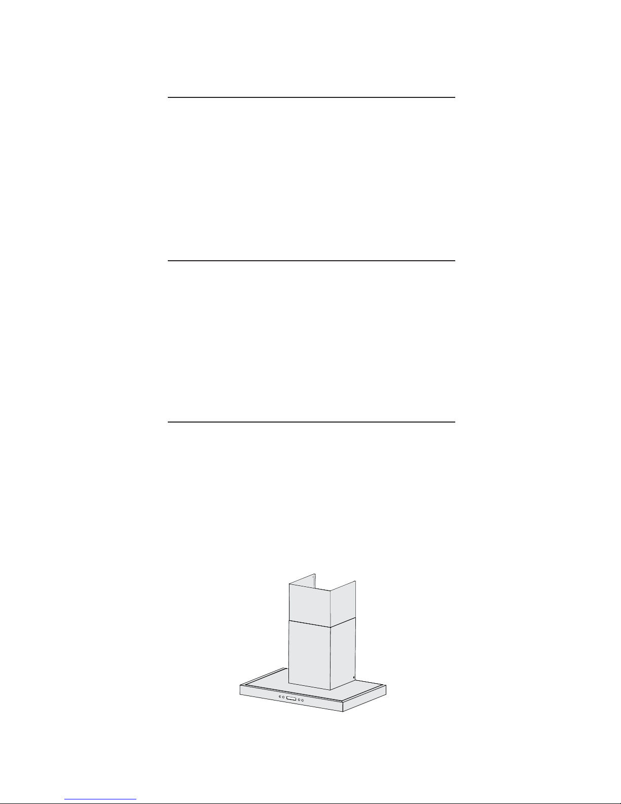
TABLE OF CONTENTS
Important Safety Instructions ................................
Ducting...................................................................
Installation..............................................................
Operation ..............................................................
Lamp Replacement ...............................................
Cleaning and Maintenance ...................................
Troubleshooting ....................................................
Warranty ................................................................
2
3
4-8
9
10
10
11
12
Instrucciones de Seguridad Importantes ...............
Ubicar el Conducto.................................................
Instalción................................................................
Operación...............................................................
Reemplazar la Bombilla ........................................
Limpieza y Mantenimiento ....................................
Resolución de Problemas .....................................
Garantía ...............................................................
ENGLISH
FRANÇAIS
ESPAÑOL
1
Consignes importantes relatives à la sécurité......
Conduits ...............................................................
Installation ............................................................
Fonctionnement....................................................
Remplacement de l'ampoule................................
Nettoyage et entretien..........................................
Dépannage...........................................................
Garantie................................................................
14
15
16-20
21
22
22
23
24
26
27
28-32
33
34
34
35
36
DWRH302SSST

IMPORTANT SAFETY INSTRUCTIONS
READ AND SAVE THESE INSTRUCTIONS
FOR DOMESTIC COOKING ONLY
WARNING
WARNING
TO REDUCE THE RISK OF FIRE, ELECTRIC SHOCK,
OR INJURY TO PERSONS, OBSERVE THE FOLLOWING:
1. Use this unit only in the manner intended by the manu-
facturer. If you have questions, contact the manufacturer at
the address or telephone number listed in the warranty.
2. Before servicing or cleaning the unit, switch the power
off at the service panel. Lock and tag the service panel to
prevent power from being switched on accidentally.
3. Installation work and electrical wiring (including switch
location) must be done by a qualified person(s) in accor-
dance with all applicable codes and standards.
4. To prevent backdrafting, provide sufficient air for proper
combustion and exhausting of gases through the flue (vent)
of the fuel burning equipment. Follow combustion equip-
ment standards such as those published by the National
Fire Protection Association (NFPA,) the American Society
for Heating, Refrigeration and Air Conditioning Engineers
(ASHRAE,) and local codes.
5. This product may have sharp edges. Be careful to avoid
cuts and abrasions during installation and cleaning.
6. When cutting or drilling into a wall or ceiling, do not dam-
age electrical wiring and other hidden utilities.
7. Ducted fans must always be vented to the outdoors.
8. Use only metal ductwork.
9. This unit must be grounded.
TO REDUCE THE RISK OF A RANGE TOP GREASE
FIRE:
1. Never leave surface units unattended. Rapid boiling
causes smoke and grease spills that may ignite. Heat oils
slowly on a low or medium setting.
2. Always turn hood ON when cooking at high heat or when
flambéing food.
3. Clean the ventilating fans frequently. Do not allow grease
to accumulate on the fan, fan blades and filter.
4. Use the proper pan size. Always use cookware appropri-
ate for the size of the surface element.
TO REDUCE THE RISK OF INJURY TO PERSONS IN
THE EVENT OF ARANGE TOP GREASE FIRE, OB-
SERVE THE FOLLOWING:*
1. SMOTHER FLAMES with a close-fitting lid, cookie sheet,
or metal tray, then turn off the burner. BE CAREFUL TO
AVOID BURNS. If the flames do not go out immediately,
EVACUATE THE AREAAND CALL THE FIRE DEPART-
MENT.
2. NEVER PICK UPA FLAMING PAN. You may get burned
or spread the fire.
3. DO NOT USE WATER, including wet dishcloths or tow-
els; a violent steam explosion could result.
4. Use an extinguisher ONLY if:
A. You know you have a Class ABC extinguisher and you
already know how to operate it.
B.The fire is small and contained in the area where it
started.
C. The fire department has already been called.
D. You can fight the fire with your back to an exit.
*Based on “Kitchen Fire Safety Tips” published by NFPA.
CAUTION
1. To reduce risk of fire and to properly exhaust air, be sure
to duct air outside. Do not vent exhaust air into spaces
within walls or ceilings, or into attics, crawl spaces, or
garages.
2. Take care when using cleaning agents or detergents.
3. Avoid using food products that produce flames under the
range hood.
4. For general ventilating use only. Do not use to exhaust
hazardous or explosive materials and vapors.
5. To avoid motor bearing damage and noisy / unbalanced
impellers, keep drywall spray, construction dust, etc. off the
power unit.
6. Your hood motor has a thermal overload which will
automatically shut off the motor if it becomes overheated.
The motor will restart when it cools down. If the motor con-
tinues to shut off and restart, have the hood serviced.
7. To best capture cooking impurities, the bottom of the
hood should be a minimum of 26” and a maximum of 34”
above the cooking surface.
8. Two installers are recommended because of the large
size and weight of this hood.
9. Please read specification label on product for further
information and requirements.
Installer: Leave this manual with the homeowner.
Homeowner: Cleaning, maintenance, and operating instructions begin on page 3.
2
1) If it is necessary to use an extension cord, use only a
3-wire extension cord that has a 3-blade electrical plug, and
3-slot power outlet that will accept the plug on the appliance.
The marked rating of the extension cord must be equal to or
greater than the electrical rating of the appliance. Otherwise,
do not use an extension cord.
GROUNDING INSTRUCTIONS
1. Read all instructions before using the appliance
2. Install or locate this appliance only in accordance with the
provided installation instructions.
3. Clean range hoods frequently. Grease should not be allowed
to accumulate on the range hood or filters.
4. Always turn the fan on when flambéing foods on the range.
5. This appliance is suitable for use in combination with both
gas and electric cooking equipment.
6. Use care when cleaning the range hood filter. Corrosive
cleaning agents, such as lye-based oven cleaners, may dam-
age the filter.

3
DUCTING
WARNING!
FIRE HAZARD
1. NEVER implement ducting in a space between walls, crawl
spaces, attics or garages. All exhaust must be vented outside.
Use metal ducting only. Fasten all connections with sheet
metal screws and certified silver tape or duct tape.
2. See Fig. 1 below for placement of ducting and electrical
cutout in wall. For a non-ducted installation, DO NOT cut a duct
access hole.
PREPARE THE HOOD
A
B
C
D
E
F
G
H
FIG. 1
ROOF CAP
DECORATIVE
FLUE
6" ADAPTER
WALL CAP
26"~34"ABOVE
COOKING SURFACE
ROUND
DUCT
HOOD
ROUND ELBOW
Unpack hood and check contents.
You should receive:
1 - Hood
2 - (A) Decorative Flue Assembly
1 - Parts Bag containing:
2 - (B) Flue Mounting Bracket
2 - (C) Mounting Screws (M3 x 8mm Pan Head)
2 - (D) Mounting Screws (M4 x 8mm Round Head)
2 - (E) Mounting Screws (ST4 x 12mm Self Tapping)
2 - (F) Mounting Screws (ST4 x 35mm Self Tapping)
4 - (G) Drywall Anchors (Φ6 x 30mm & Φ(H) 8 x 35mm)
1 - Installation Instructions
Determine whether the hood will discharge vertically or
horizontally. For vertical or horizontal discharge, run ductwork
between the hood location and roof cap or wall cap.
A minimum 6” round duct must be used to maintain maximum
airflow efficiency.
Always use rigid type metal ducts only.
Whenever possible, reduce the number of transitions and turns
in the ducting. If a long duct length is required, increase the
duct size from 6” to 7”.
If elbows or bends are required; install them as far away from
the hood as possible.
Minimum mounting height between the range and the bottom
of the hood should be no less than 26”.
Maximum mounting height between the range and the bottom

1) MARK REFERENCE POINTS ON WALL
The bottom of the range hood must sit between 26”
(min) and 36” (max) above the stove top. The screw
holes must be situated 13-1/2” above the point where
the bottom of the range hood will hang. The screw
holes for mounting the range hood must be 9” apart.
Refer to Fig. 2 and mark these reference points on
the wall before installing the range hood. Then, drill
2 screws into the wall but not tightly: you must leave
some of the screw (roughly half an inch) out of the wall
until after the range hood is mounted.
2) MOUNTING THE RANGE HOOD ON THE
WALL
Before mounting the range hood on the wall please take out
the filters and remove any plastic or styrofoam found inside
the range hood (see Fig. 3 and Fig. 4.) Leave the filters out
until Step 3 is finished.
FIG. 4 - PEEL OFF PLASTIC FROM THE FLUES
FIG. 2
26” min
34” max
CEILING
9”
13-1/2”
F & HF & H
INSTALLATION INSTRUCTIONS
4
A
Separate the extension flue by
pulling it upward.
19-5/8”
19-1/8”
Remove the plastic
found on the flues.
FIG. 3
Remove filters and
styrofoam pieces
from inside the
rangehood.
1.Push in tab
2.Pull downward

INSTALLATION INSTRUCTIONS
3) MOUNTING TO THE WALL
Position the range hood by hanging it onto the screws. Once it is level, tighten the screws all the way from inside the
range hood (Fig 5.) Please note: a stubby screwdriver may be required to access the screws from inside the range hood.
Once the range hood is securely fastened, the filters can be put back in. At this point, the range hood should match Fig. 6.
5
Please tighten the 2 screws from the inside.
FIG. 5
26” min
34” max
CEILING
9”
13-1/2”
FIG. 6
LEVELING DEVICE
When mounting hood on the wall, the level can be adjusted
by turning the two screws on the motor housing.
F & H F & H

INSTALLATION INSTRUCTIONS
4) MOUNTING THE DECORATIVE FLUE (REQUIRES 2 PEOPLE)
Before you mount the decorative flue to the range hood, fasten the exhaust tubing to
the blower housing and make sure all ducting is correct (see Fig. 7.) Have a qualified
electrician connect the power supply (see Fig. 8.) Next, fasten the decorative flue onto
the range hood. DO NOT SEPARATE THE EXTENSION FLUE! Have one person hold
the flue and the other person align the holes on the decorative flue with the holes on
the range hood brackets. Fasten the 2 screws on each side (see Fig. 9.)
6
Connect house power cable to range hood wiring,
Ground Wire: GREEN
Fire Wire : BLACK
Zero Line : WHITE
/
1
FIG. 8 - Wiring diagram
CEILING
FIG. 7
Blower
Housing
Exhaust
tubing/duct
STEP.1
Align holes
STEP.2
Tighten screw
on each side
Flu
Rangehood
WALL
FINAL
Flu
Rangehood
WALL
FIG. 9 - Side of unit
WALL
ELECTRICAL
ACCESS
C

Locate the mounting bracket and center it on the wall just below the ceiling (Option A)
or on the ceiling with the hooks facing downward (Option B) using 2 screws (see Fig.
10.) Once the bracket has been mounted on the wall or ceiling, raise the extension flue
toward the ceiling and line up the holes in the flue with the holes in the mounting bracket.
Secure the extension flue by fastening it with 2 screws on each side (see Fig. 11.) Final
install see Figs. 12 and 13.
5) MOUNTING BRACKET INSTALL
INSTALLATION INSTRUCTIONS
7
CEILING CEILING
FIG. 10
FIG. 11
Raise
extension
flue toward
ceiling and
align the holes
then secure it
in place with 2
screws on each
side.
Fix the
mounting
bracket to
the wall or
ceiling using
2 screws.
1. Mount these screws to the wall
to secure the mounting
bracket
2. Align holes and secure
flue to the bracket with 2
screws on each side
FIG. 12 - Bracket on wall (Option A)
12-1/2”
8-1/2”
1. Mount these screws to the
ceiling to secure the mounting
bracket.
2. Align holes and secure
flue to the bracket with 2
screws on each side
FIG. 13 - Bracket on ceiling (Option B)
12-1/2”
8-1/2”
E & G x 2
DD
E & G x 2 E & G x 2
DDD D

5) FINAL INSTALLATION IMAGE
INSTALLATION INSTRUCTIONS
8
26” min
34” max
CEILING
9”
13-1/2”
FIG. 14
12-1/2”
8-1/2”
DD
E & G x 2
F & H x 2
CC
Questo manuale è adatto per i seguenti modelli
2
Indice


