3SimpliFire • Inception Decorative Front Instructions (Chateau Forge, Halston) • 4200-930 • Rev B • 8/23
2. Remove mounting bracket assembly and bend the
mounting bracket assembly vertically to separate the
left and right brackets (B and C). See Figure 3.
Do not bend mounting bracket tabs.
Discard screws and shipping brackets. See Figure 3.
B. Installation
1. Remove components from package. Components in-
cluded will depend on the decorative front being installed.
The mounting brackets are secured to a shipping bracket
located on the back side of the decorative front. Remove
shipping bracket using 1/4 in. nut driver and remove
mounting brackets from packaging.
MOUNTING
BRACKETS
MOUNTING
SCREWS (A)
(B & C)
SIDE PANELS
(D & E)
Figure 5 Attach Side Panels
3. Remove side panels (D and E) from appliance compo-
nent box. See Figure 3.
4. Attach mounting brackets (B and C) and side panels
(D and E) to appliance using the four mounting screws
(A). See Figure 5. Locate the laser-cut number 36 on
the bracket which represents the size of the decora-
tive front. This marking also indicates the top of the
bracket. Install the bracket so that the front edge of the
bracket sits ush with the desired depth of the decora-
tive front. Mounting tabs should extend at least 1/8
inch past desired depth. See Figure 6. Side panels
install over the mounting brackets using the same
mounting screws (A).
For example: If the decorative front is to t tight
against the appliance (Inside Fit), install the brackets
ush with the face of the appliance. If the decora-
tive front is to t up tight against a nishing material
with maximum thickness of one inch (Overlap Fit), the
brackets should be ush with the face of the mate-
rial. For both inside t and overlap t applications, the
mounting tabs should extend at least 1/8 inch past
desired depth. Refer to Section A, “Finishing Material”
for more information.
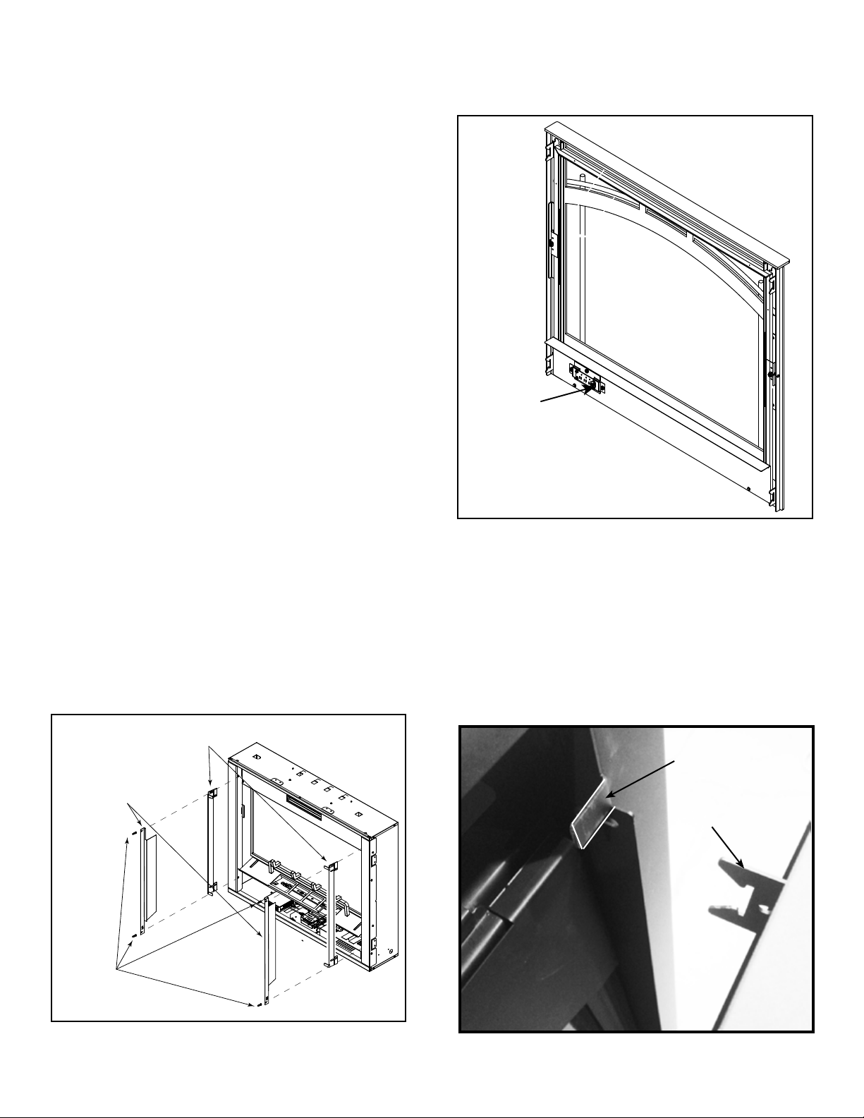
5. Connect the wire harness at the lower right of the front
to the corresponding connector from the appliance,
See Figure 5.
6. Install the decorative front to the mounting brackets
by engaging the brackets mounted on the decorative
front assembly to the mounting brackets located on
the appliance. See Figure 7. Ensure the decorative
front is properly attached and securely positioned on
the appliance.
NOTE: Before installing decorative front, make sure the
appliance junction box master switch is ipped to the
ON position.
Figure 6 Install Decorative Front
Figure 7 Install Decorative Front
MOUNTING TABS (4)MOUNTING TABS (4)
SLOTTEDSLOTTED
BRACKETS (4)BRACKETS (4)