Sirocco 16" Manuale

DECORATIVE FUEL EFFECT
APPLIANCE
THIS IS A NATURAL GAS (G20)
APPLIANCE FOR USE IN GB AND IE ONLY
AT A SUPPLY PRESSURE OF 20mbar.
MODELS 16” AND 18”
REMOTE AND MANUAL VERSIONS
USER’S, INSTALLATION
AND SERVICE MANUAL
PLEASE KEEP THESE INSTRUCTIONS IN A SAFE
PLACE FOR FUTURE REFERENCE
VI-06-09

2
TABLE OF CONTENTS
IMPORTANT NOTES___________________________________________ 3
USER’S SECTION _____________________________________________ 4
FUEL EFFECT ________________________________________________ 4
GAS CONSUMPTION __________________________________________ 4
OPERATING INSTRUCTIONS -MANUAL VERSION _______________ 4
TO LIGHT THE FIRE _________________________________________________4
SELECT THE BURNER FLAME LEVEL _________________________________4
TO TURN OFF_______________________________________________________4
CLEANING _________________________________________________________4
OPERATING INSTRUCTIONS - REMOTE CONTROL VERSION___________ 5
TO LIGHT THE FIRE _________________________________________________5
TO SELECT THE REQUIRED FLAME LEVEL ____________________________5
TO TURN OFF_______________________________________________________5
OXYGEN DEPLETION SYSTEM__________________________________ 5
FUEL BED ASSEMBLY _________________________________________ 6
INSTALLATION SECTION______________________________________ 16
1 GENERAL DATA_________________________________________ 16
2 GENERAL INSTALLATION REQUIREMENTS __________________ 16
3 CHECK CARTON CONTENTS ______________________________ 17
4 THE FIREPLACE ________________________________________ 17
5 GAS SUPPLY PIPE_______________________________________ 18
6 APPLIANCE INSTALLATION _______________________________ 18
6.5 CHECK FOR GAS SOUNDNESS ____________________________ 18
6.6 FUEL BED ASSEMBLY____________________________________ 18
7 FUNCTIONAL CHECKS ___________________________________ 18
8 CHECK FOR SPILLAGE ___________________________________ 19
9 FINAL CHECK AND CUSTOMER BREIFING ___________________ 19
10 SERVICING_____________________________________________ 19
10.1 TO REMOVE THE BURNER UNIT ___________________________ 20
10.2 TO REMOVE THE PILOT BURNER ASSEMBLY ________________ 20
10.3 TO REMOVE THE GAS TAP / FSD / IGNITION UNIT ____________ 20
11 MAINTENANCE SPARES __________________________________ 21
12 FAULT FINDING _________________________________________ 21
VI-06-09

3
IMPORTANT NOTES
1. SOFT WALL COVERINGS, (e.g. EMBOSSED
VINYLS etc.) WHICH HAVE A RAISED
PATTERN, ARE EASILY AFFECTED BY HEAT
AND MAY SCORCH OR BECOME
DISCOLOURED WHEN CLOSE TO A
HEATING APPLIANCE. PLEASE BEAR THIS
IN MIND WHEN RE-DECORATING.
2. AS WITH ANY GAS FIRE, THIS APPLIANCE
MUST BE INSTALLED BY A COMPETENT
PERSON (e.g. IN GB A C.O.R.G.I. MEMBER)
IN ACCORDANCE WITH THE INSTALLATION
INSTRUCTIONS AND THE LATEST EDITION
OF THE GAS SAFETY (INSTALLATION AND
USE) REGULATIONS OR THE RULES IN
FORCE.
3. IF THE FIRE IS INTENDED TO BE
INSTALLED TO A FIREPLACE THAT WAS
PREVIOUSLY USED FOR BURNING SOLID
FUELS THE CHIMNEY MUST BE SWEPT
PRIOR TO INSTALLATION.
4. THE FIRE MUST NOT BE INSTALLED
DIRECTLY ONTO CARPETS OR OTHER
COMBUSTIBLE MATERIALS.
5. THE FIRE MUST STAND ON A NON-
COMBUSTIBLE HEARTH. THE HEARTH
MATERIAL MUST BE A MINIMUM OF 12.5mm
THICK. ITS TOP SURFACE SHOULD BE
50mm ABOVE THE FLOOR LEVEL TO
DISCOURAGE THE PLACING OF RUGS,
CARPETS OR OTHER COMBUSTIBLE
MATERIALS OVER IT. THE FINISHED
HEARTH LEVEL MUST EXTEND 300mm
BEYOND THE VERTICAL FACE OF THE
FIREPLACE OPENING FOR BOTH THE 16”
AND 18” MODELS. THE MINIMUM WIDTH OF
THE HEARTH MUST BE 650mm FOR THE 16”
VERSION AND 700mm FOR THE 18"
VERSION.
6. THE FIRE MUST NOT BE FITTED AGAINST A
COMBUSTIBLE WALL.
7. THE MINIMUM HEIGHT ABOVE THE TOP
SURFACE OF THE HEARTH FOR ANY
PROJECTION (e.g. SHELF etc.) 150mm DEEP
MADE FROM WOOD OR ANY OTHER
COMBUSTIBLE MATERIAL IS 766mm. FOR
COMBUSTIBLE PROJECTIONS ABOVE
150mm DEPTH ADD 12.5mm TO THE ABOVE
CLEARANCE FOR EVERY 25mm OF
ADDITIONAL PROJECTION DEPTH.
8. NEVER THROW PAPER OR OTHER
MATERIAL ONTO THE FIRE.
9. IT SHOULD BE APPRECIATED THAT
ALTHOUGH THIS APPLIANCE CONFORMS
TO ALL THE REQUIRED STANDARDS, IT IS
A DECORATIVE FUEL EFFECT HEATING
APPLIANCE WITH AN OPEN FLAME AND
CERTAIN PARTS OF ITS SURFACE WILL
BECOME HOT. A SUITABLE GUARD, WHICH
COMPLIES WITH THE REQUIREMENTS OF
B.S. 8423 IS THERFORE RECOMMENDED
FOR THE PROTECTION OF THE VERY
YOUNG, THE ELDERLY OR THE INFIRM.
SUCH A GUARD IS ALSO RECOMMENDED
FOR THE PROTECTION OF PET ANIMALS.
10. ALWAYS SWITCH THE FIRE OFF AND
ALLOW SUFFICIENT TIME FOR IT TO COOL
DOWN BEFORE HANDLING ANY
COMPONENTS.
11. PLEASE NOTE THAT THIS APPLIANCE
RETAINS HEAT FOR A LONG TIME AFTER IT
HAS BEEN TURNED OFF.
PLEASE NOTE
On first lighting your new fire, a slight odour may
occur due to its new condition. This is quite
normal and will disappear after a few hours use.
After some hours use, the ceramic coal pieces
may change colour. This is quite normal.
Some granules will be lost during the lifetime of
the appliance while cleaning etc. to allow for
replacement, surplus granules are supplied with
your new appliance. Keep these in a safe place.
In order to obtain an authentic flame effect, the
burner on this appliance is a granular filled pan
type. Due to the nature of this kind of burner,
there will be various “popping” and flame noises
not usually associated with ordinary gas fires.
As in a real coal fire, these noises are perfectly
normal.
The fire has been designed to give years of
trouble free service. To maintain its optimum
performance, advantage should be taken of the
regular servicing and inspection facilities
available for gas appliances. Annual servicing is
recommended. These instructions are provided
to help you in operating the fire and should be
kept in a safe place.
VI-06-09

4
USER’S SECTION
FUEL EFFECT
This fire is supplied with ceramic fuel effect pieces
to simulate a real fire and a granular bed to
provide even flame distribution across the whole of
the bed. These items are safe to handle and the
coals are designed for easy re-fitting after
removal.
GAS CONSUMPTION
This fire has a maximum gas input of 6.9 kW,
which is equal to approximately 4.25 hours use for
one therm of natural gas.
OPERATING INSTRUCTIONS -
Manual Version
Figure 1
OFF
IGNITION
HIGH
LOW
For your safety, the fire is fitted with a Flame
Supervision Device (FSD), which will shut off the
gas supply if for any reason the pilot is
extinguished. This device incorporates a fixed
probe, which senses heat from the pilot burner
flame. If the probe is cool, the device will prevent
any gas flow unless the control knob is pushed in
at the IGNITION position.
If for any reason the flames go out or if the fire has
been turned off for any reason, always WAIT FOR
3 MINUTES before attempting to relight.
TO LIGHT THE FIRE
1. From the off position, SLOWLY push in
and turn the control knob anti-clockwise to
activate the spark at the IGNITION
position.
2. Keep the control knob pressed in at this
position for approximately 10 – 20
seconds to allow the Flame Supervision
Device to warm.
3. Release the control knob. The pilot should
remain lit independently.
SELECT THE BURNER FLAME LEVEL
NOTE: When first turned on the flames will appear
predominately blue. The coal bed will take time to
warm up. Although some glow will be seen after 5
– 10 minutes, the full effect will only be apparent
after a somewhat longer time.
1. After lighting the pilot as described above,
turn the control knob anti-clockwise to the
HIGH position. The fire will now ignite.
2. To decrease the amount of flame push the
control knob in slightly and turn to the
LOW position. The fire can now be used at
any desired setting at any position
between minimum (LOW) and maximum
(HIGH).
TO TURN OFF
1. Push in and turn the control knob
clockwise to the OFF position to
extinguish the flames and the pilot flame.
2. If desired he pilot flame can be left on to
make it quicker and easier to light the fire.
Although the pilot is using gas all the time
it is on, the amount used is minimal. To do
this turn the control knob to the IGNITION
position instead of the OFF position as
described above. If the fire is to be
switched OFF for long periods, it is
recommended that the control knob be
turned to the OFF position.
CLEANING
All cleaning MUST be carried out when the fire is
cold. NOTE: Heat is retained for some time after
the fire is switched OFF. Clean the surround and
fender parts with a slightly damp cloth and then
dry. Abrasive cleaners should NOT be used.
Normally the fire should only need dusting. Light
coatings of soot will usually be burnt off during the
normal operation of the fire. If however, particles of
mortar from the chimney accumulate these should
be removed from the coals and back brick by
dismantling them and cleaning with a soft brush. If
you remove the fuel effect pieces, then do so in
the reverse order to that shown in the fuel bed
fitting instructions (pages 9 – 15).
VI-06-09

5
If soot or other foreign matter has become mixed
with the granular materials and cannot be removed
by hand, remove the contaminated layer and
replace with a clean layer from the bag of granules
supplied with the fire. When levelling ensure that
none of the granules are pushed into the pilot
burner outlet.
If large pieces of debris are found any where in the
fireplace, the chimney and appliance should be
inspected and serviced by a competent person
before further use.
OPERATING INSTRUCTIONS -
Remote Control Version
TO LIGHT THE FIRE
(Ensure the battery is connected and batteries are
also in the handset)
To light the fire, point the handset to the sensor on
the front your fire. Push and hold the two buttons
together, on the left hand side of the handset. The
fire will give out a beep sound and you can release
the buttons. After a few seconds you will hear the
clicking spark to the pilot light. Once the pilot is lit
the fire main burner will come on to the high
position (this whole process will take no more than
20 seconds).
TO SELECT THE REQUIRED FLAME
LEVEL
To turn down the fire, point the handset to the
sensor on your fire then push and hold the minus
button (small flame), if you release immediately
the flame will go to low if you hold the flame will
lower slowly and you can release the button to
your desired position.
To turn the fire up, point at the sensor, push the
plus button until the desired flame height is
reached.
The fire may be left in the standby mode (pilot
only) by pressing the small round button on the
handset.
TO TURN OFF
To turn your fire off, point the handset at the
sensor and push the top left button. The
fire will go out.
OXYGEN DEPLETION SYSTEM
If the Oxygen Depletion System (ODS) operates,
i.e. shuts off the gas supply to the fire, WAIT FOR
THREE MINUTES and follow the operating
instructions on pages 4 and 5.
The ODS is designed to shut off the gas supply to
the burner if the oxygen content of the room falls
below a certain level. If it continues to operate then
contact your installer to have the fire and flue
system checked.
SERVICING AND MAINTENANCE
If your fire requires servicing or maintenance,
please contact your supplier quoting the model
name (Streamline 3) and the serial number. Both
of which can be found on the data badge, which is
located next to the control knob behind the ash
pan cover.
BATTERY REPLACEMENT
USE ALKALINE BATTERIES ONLY (9 Volt PP3)
IN THE HANDSET
VI-06-09

6
FUEL BED ASSEMBLY
The granular dispersal compound provided in a
plastic bag should be poured into the cast iron tray
and gently levelled to within 5mm of the lip of the
tray. Remove any spilt granules from under or
around the and particularly from the pilot
assembly. ALWAYS ENSURE THAT THE
GRANULAR MATERIAL LIES LOOSELY AND IS
NOT ALLOWED TO COMPRESS.
Sprinkle the ember material across the top surface
of the granular material. The ember material is in a
separate smaller bag.
The Streamline 3 is available with 3 different fuel
effects as follows:
Coal Made up of 25 coals. Turn to page
9 for layout instructions.
Pebbles Made up of 25 pebbles. Turn to
page 11 for layout instructions.
Logs Made up of 13 coals and 7 logs
and pinecones. Turn to page 13
for layout instructions.
COAL LAYOUT
Figure 5
1. Place the two centre ceramic pieces as shown. The angled edge should be in line with
the edge of the burner tray casting. NOTE: On the 18” version there should be a gap of
approximately 50mm between the centre ceramics.
VI-06-09

7
A
Figure 6
2. Place two rows of 4 coals as shown above ensuring that the front coals overhang the
edge of the casting at the front and the rear coals are touching the rear wall of the
fireplace or convector box. Note: on the 16” version the right hand front coal is a
narrow coal different to the rest to allow it to be fitted at the side of the pilot (marked `A’
above).
Figure 7
3. Place a row of 5 coals along the top of the centre ceramics as shown above.
VI-06-09

8
Figure 8
4. Place two rows of 3 coals bridging the gaps in the rows beneath as shown above. The
rear row of coals should be touching the rear wall of the fireplace or convector box.
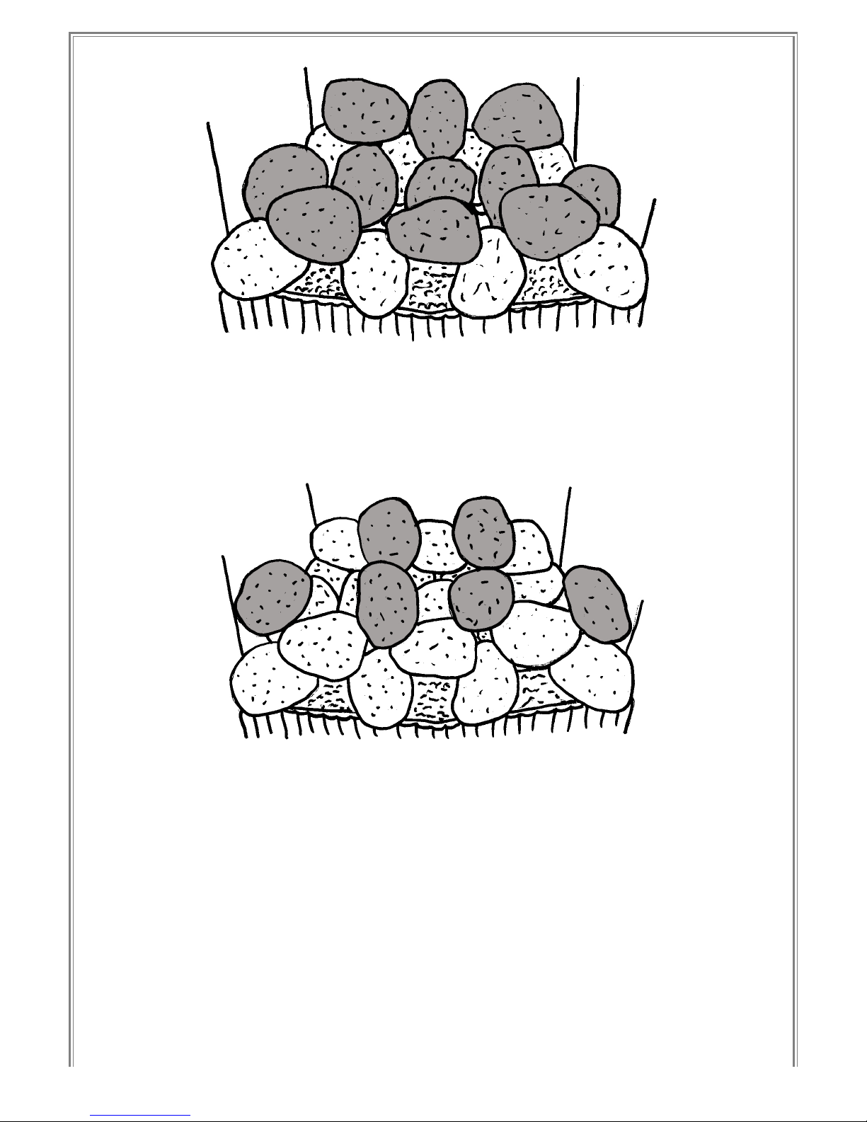
Figure 9
5. Place another row of 2 coals bridging the gaps in the rear row of coals placed in step
4. Place a row of 4 coals bridging the gaps in the front row of coals placed in step 4.
VI-06-09

9
PEBBLE LAYOUT
Figure 10
1. Place the two centre ceramic pieces as shown. The angled edge should be in line with
the edge of the burner tray casting. On the 18” version there should be a gap of
approximately 50mm between the centre ceramics.
A
Figure 11
2. Place two rows of 4 pebbles as shown above ensuring that the front pebbles overhang
the edge of the casting at the front and the rear pebbles are touching the rear wall of
the fireplace or convector box. Note: on the 16” version the right hand front pebble is a
narrow pebble different to the rest to allow it to be fitted at the side of the pilot (marked
`A’ above).
VI-06-09
10
Figure 12
3. Place a row of 5 pebbles along the top of the centre ceramics as shown above. Then
place a further two rows of 3 pebbles bridging the gaps in the rows beneath as shown
above. The rear row of pebbles should be touching the rear wall of the fireplace or
convector box.
Figure 13
4. Place another row of 2 pebbles bridging the gaps in the rear row of pebbles placed in
step 3. Place a row of 4 pebbles bridging the gaps in the front row of pebbles placed in
step 3.
VI-06-09
Questo manuale è adatto per i seguenti modelli
1
Indice
Altri manuali Sirocco Camino da interno

Sirocco
Sirocco Royal Solo Apex Manuale utente

Sirocco
Sirocco Streamline 3 Guida

Sirocco
Sirocco Eco4 E4 HE Plus Guida

Sirocco
Sirocco Mystique ECO 4 Manuale per l'uso e la cura

Sirocco
Sirocco Fire Royal 1000 Manuale utente

Sirocco
Sirocco REMOTE ECO 1 Supplemento

Sirocco
Sirocco Vola 400HE Guida

Sirocco
Sirocco Eco3 Guida

Sirocco
Sirocco SCENIC Spirit Guida


