SITEMA KRGP Series Manuale utente

Operating Manual
Safety Locks series KRGP
Pneumatic / compressive load
Original instructions BA-S12-en-1-15
© SITEMA GmbH & Co. KG . G.-Braun-Straße 13 . 76187 Karlsruhe (Germany) . Phone: +49(0)721/98661-0 . Fax: -11 . www.sitema.com 1/28
Operating Manual BA-S12
Safety Locks series KRGP
þhigh holding forces through self-reinforcing clamping
þfor static loads
þcompact design

Table of contents
1 General ......................................................................................................4
1.1 About this manual............................................................................. 4
1.2 Associated documents .................................................................... 4
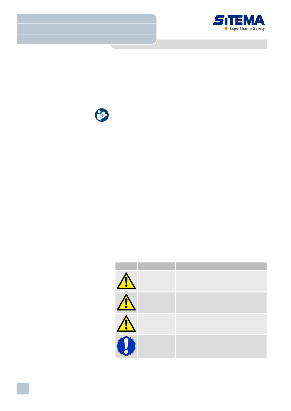
1.3 Explanation of symbols..................................................................... 4
1.4 Warranty ........................................................................................... 5
2 Safety.........................................................................................................5
2.1 Intended use..................................................................................... 5
2.2 Regular performance testing ............................................................ 6
2.3 Responsibility of the machinery manufacturer.................................. 7
2.4 Personnel requirements ................................................................... 7
2.5 Personal protective equipment ......................................................... 7
2.6 Labeling ............................................................................................ 8
3 Technical data...........................................................................................8
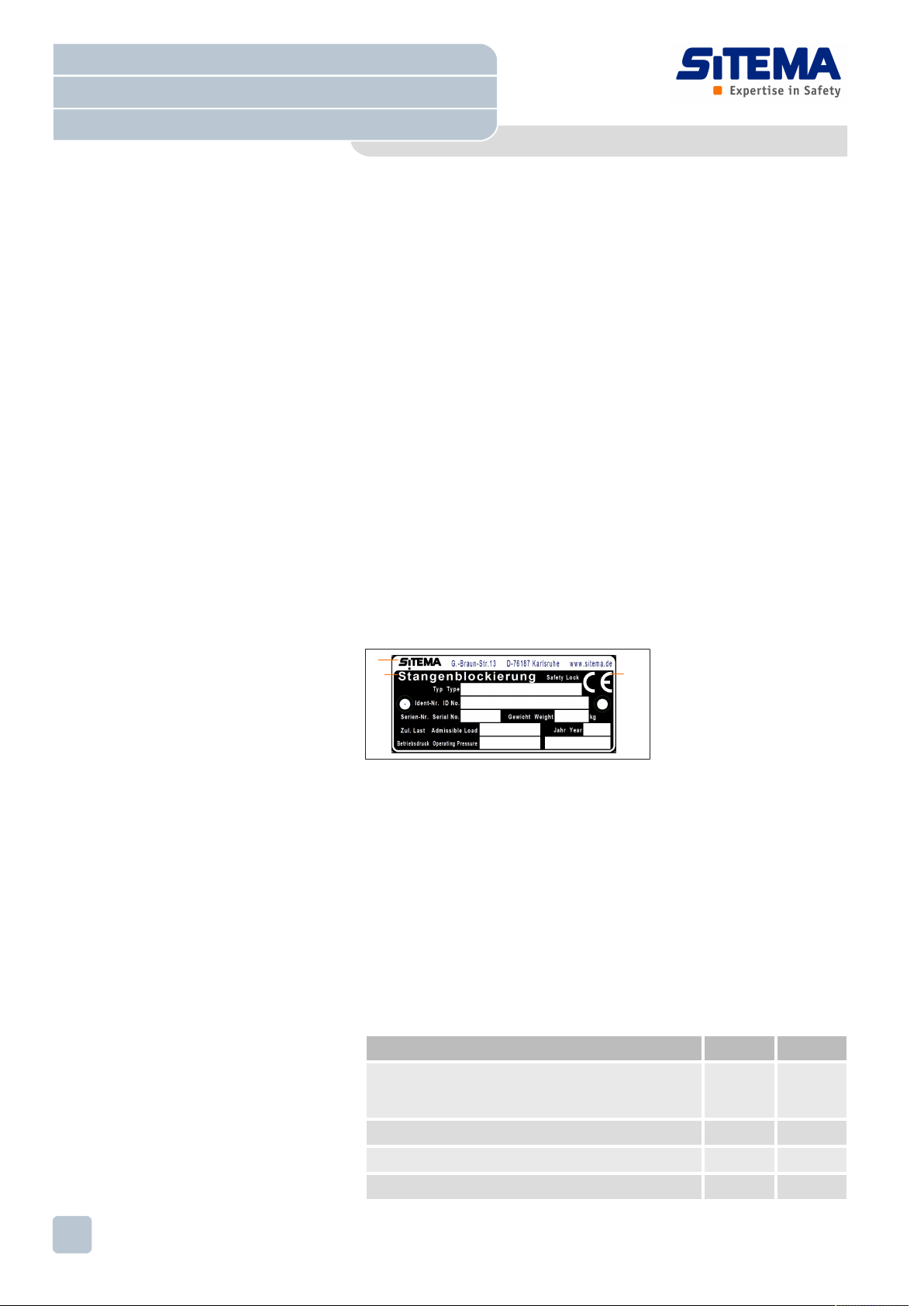
3.1 Name plate ....................................................................................... 8
3.2 Pressure fluid ................................................................................... 8
3.3 Operating conditions......................................................................... 9
3.4 Emissions ......................................................................................... 9
3.5 Service life ........................................................................................ 9
4 Design and function ...............................................................................10
4.1 KRGP (pressure version) design.................................................... 10
4.2 Function.......................................................................................... 10
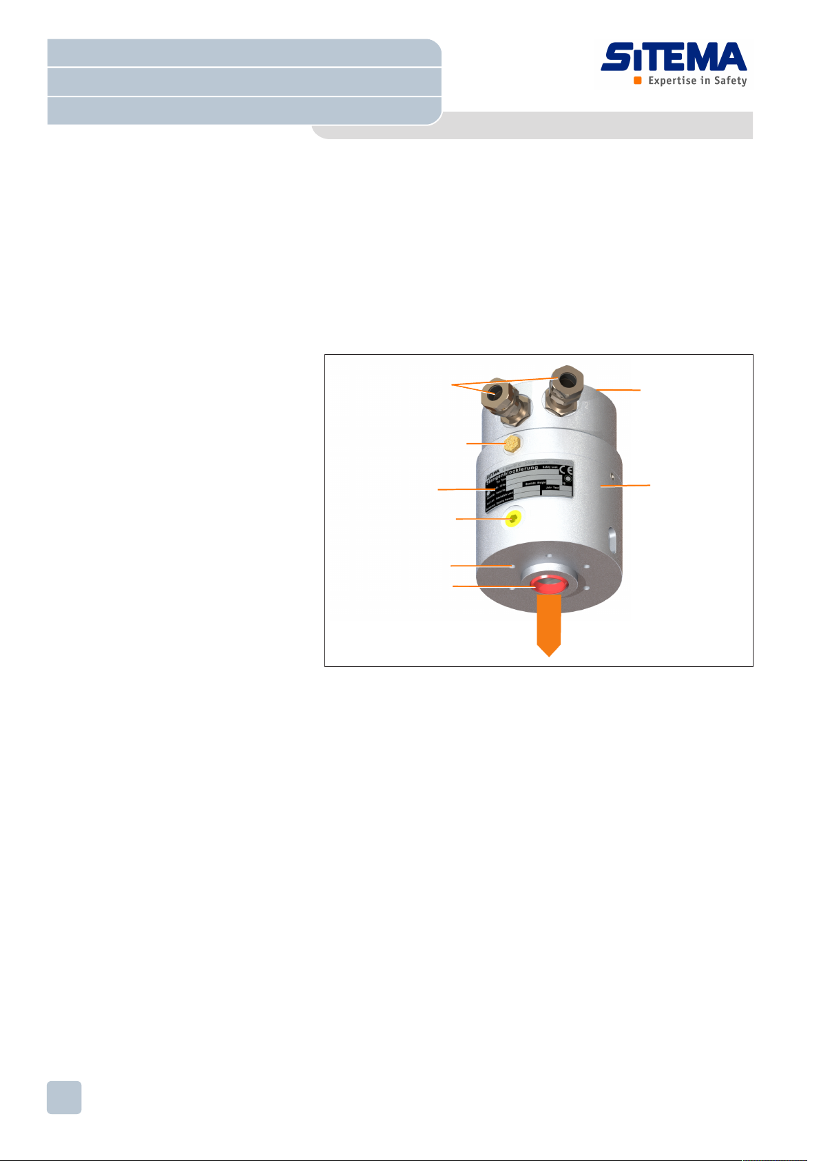
4.3 Layout ............................................................................................ 11
4.4 Ports ............................................................................................... 12
5 Transport, packaging and storage........................................................13
5.1 Safety notices for transport............................................................. 13
5.2 Packaging....................................................................................... 13
5.3 Transport ........................................................................................ 13
5.4 Storage ........................................................................................... 14
6 Preconditions for use.............................................................................14
6.1 Location requirements .................................................................... 14
6.2 Requirements for the clamping rod ................................................ 15
7 Installation...............................................................................................16
7.1 Feeding in clamping rod ................................................................. 16
7.2 Attach Safety Lock.......................................................................... 17
7.3 Making pressure connection........................................................... 18
7.4 Checking port T ............................................................................. 19
7.5 Connect proximity switch (optional equipment in special designs)......
20
7.6 Checking installation....................................................................... 20
8 Performance test ....................................................................................20
8.1 Testing holding force ...................................................................... 21
8.2 Testing proximity switch functionality ............................................. 22
9 Putting into service ...............................................................................23
9.1 Releasing the clamp ....................................................................... 23
9.2 Securing the load............................................................................ 24
9.3 Taking up the load .......................................................................... 24
10 Inspection, maintenance and cleaning.................................................24
10.1 Inspection ...................................................................................... 24
10.2 Maintenance ................................................................................... 25
10.3 Cleaning ......................................................................................... 25
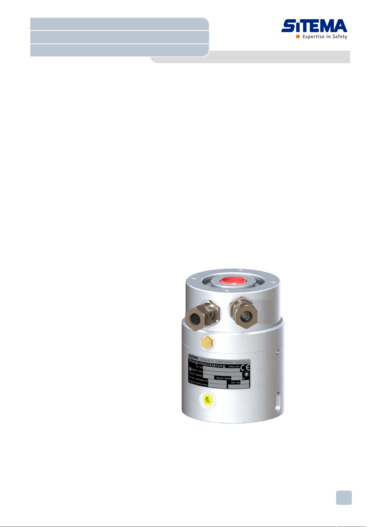
Operating Manual
Safety Locks series KRGP
Pneumatic / compressive load
Original instructions BA-S12-en-1-15
© SITEMA GmbH & Co. KG . G.-Braun-Straße 13 . 76187 Karlsruhe (Germany) . Phone: +49(0)721/98661-0 . Fax: -11 . www.sitema.com
2/28

11 Troubleshooting .....................................................................................26
12 Repairs ....................................................................................................26
13 Disassembly and disposal.....................................................................26
13.1 Disassembly ................................................................................... 27
13.2 Disposal.......................................................................................... 28
14 Technical data sheet ..............................................................................28
Operating Manual
Safety Locks series KRGP
Pneumatic / compressive load
Original instructions BA-S12-en-1-15
© SITEMA GmbH & Co. KG . G.-Braun-Straße 13 . 76187 Karlsruhe (Germany) . Phone: +49(0)721/98661-0 . Fax: -11 . www.sitema.com 3/28

1 General
1.1 About this manual
This manual enables safe handling of the Safety Lock. The manual is an inte-
gral part of the Safety Lock, and must be kept readily available to personnel
close by.
Personnel must have thoroughly read and understood this manual before
starting any work procedures. Compliance with the safety notices and other
instructions set out in this manual is essential to safe working. National acci-
dent prevention regulations and occupational health and safety requirements
apply in addition to the instructions set out in this manual.
Illustrations in this manual are intended to provide a basic understanding, and
may differ from the actual implementation.
1.2 Associated documents
You have received the following documents together with this manual:
• technical data sheet (see annex)
• EC Declaration of Conformity
• for standard designs (for special designs where appropriate): adjustment
instructions for proximity switch holders
• a dimensional drawing, where appropriate
• for modified standard designs: supplementary information
• for included proximity switches: proximity switch data sheet
Be sure to comply with the instructions and notices contained in those docu-
ments.
1.3 Explanation of symbols
Safety notices in this manual are flagged by symbols. Safety notices start with
a signal word indicating the severity of the hazard.
Symbol Signal word Meaning
DANGER! Indicates an immediate danger which will result
in death or serious injury if not avoided.
WARNING! Indicates a potential danger which may result in
death or serious injury if not avoided.
CAUTION! Indicates a potential danger which may result in
moderate or slight injury if not avoided.
NOTICE! Indicates a potential danger which may result in
damage to assets or harm to the environment if
not avoided.
Operating Manual
Safety Locks series KRGP
Pneumatic / compressive load
Original instructions BA-S12-en-1-15
© SITEMA GmbH & Co. KG . G.-Braun-Straße 13 . 76187 Karlsruhe (Germany) . Phone: +49(0)721/98661-0 . Fax: -11 . www.sitema.com
4/28

Symbol Signal word Meaning
The figurative clamping head flags up useful
tips and recommendations for safe, trouble-free
functionality.
Table1: Explanation of symbols
1.4 Warranty
SITEMA provides a 24-month warranty on the standard design version of
the Safety Lock from date of delivery. The warranty on special designs is
12months.
Shipped items which are found to be defective will be repaired free of charge
at our factory or replaced. The possibility of reimbursing any costs beyond this
warranty cover is excluded.
The actual scope of delivery may differ from the wording and illustrations
shown here where special designs are supplied, additional components are
ordered, or technical modifications are made.
Wearing parts and corrosion damage are excluded from warranty cover, as is
any damage resulting from use other than for the intended purpose. No liabil-
ity will be accepted for consequential damage or loss.
2 Safety
This chapter provides an overview of all key safety aspects for the protection
of personnel and to ensure safe, trouble-free operation. The sections covering
the individual life phases contain additional task-specific safety notices.
2.1 Intended use
The Safety Lock holds static loads.
Use in accordance with the intended purpose also means complying with all
the stipulations set out in this manual and in the associated documents.
Any use beyond or at variance to the intended use shall be considered as
misuse.
The Safety Lock is designed to hold the admissible load (M) stipulated on
the name plate and in the data sheet (or dimensional drawing). The static
weight acting on the rod must not exceed the admissible load in any operat-
ing state.
CAUTION
Danger of damage
The rod does not slip if there is an overload. Loads that exceed twice the ad-
missible load M can lead to damage on the rod and Safety Lock.
ÜDo not overload the Safety Lock.
Operating Manual
Safety Locks series KRGP
Pneumatic / compressive load
Original instructions BA-S12-en-1-15
© SITEMA GmbH & Co. KG . G.-Braun-Straße 13 . 76187 Karlsruhe (Germany) . Phone: +49(0)721/98661-0 . Fax: -11 . www.sitema.com 5/28

The Safety Lock has the advantage that it does not release under load.
The Safety Lock can normally be released in this case only if release pres-
sure is applied and the load is simultaneously lifted, i.e. if the load has al-
ready been transferred safely elsewhere. To ensure this safety advantage,
the load must have a minimum value during operation. See minimum
value F6 in “Technical data sheet TI-S12”.
WARNING
Danger in case of misuse!
Misuse of the Safety Lock can lead to dangerous situations.
ÜUse the Safety Lock only to hold loads that do not exceed the admissi-
ble load. The static weight acting on the rod must never exceed the ad-
missible load.
ÜUse the Safety Lock only in explosion-proof areas.
ÜUse the Safety Lock only for securing static loads, not for braking dy-
namic loads.
ÜDo not use the Safety Lock as a positioning device.
ÜAlways leave the rod inserted during operation.
ÜLeave the Safety Lock assembled. Do not open the Safety Lock.
ÜMaintain the Safety Lock in its delivered condition. Do not manipulate
the Safety Lock.
2.2 Regular performance testing
Regular performance testing ensures safe functioning of the Safety Lock.
Use the performance test to verify safe functioning of the Safety Lock also
after unforeseen events occur.
A performance test must be carried out in the following cases:
• after installation
• after any use at variance from the intended use
In safety applications, the functioning of the Safety Lock must be checked at
least every 6 months. Much more frequent testing may also be required de-
pending on the application parameters (degree of contamination, cycle fre-
quency, control system). In some cases even daily fully automated testing is
necessary. This detects any trouble at an early stage.
See also Chapter8Performance test [}20].
If the test finds that the Safety Lock no longer conforms to the specified prop-
erties, the stipulated safety for working on plant and other machinery is no
longer assured. The Safety Lock must be returned to SITEMA without delay
for professional servicing and acceptance testing.
Operating Manual
Safety Locks series KRGP
Pneumatic / compressive load
Original instructions BA-S12-en-1-15
© SITEMA GmbH & Co. KG . G.-Braun-Straße 13 . 76187 Karlsruhe (Germany) . Phone: +49(0)721/98661-0 . Fax: -11 . www.sitema.com
6/28

2.3 Responsibility of the machinery manufacturer
Where a machinery manufacturer integrates the Safety Lock into a machine or
plant as a safety component, the machinery manufacturer must fulfill the fol-
lowing obligations:
• Select and integrate the Safety Lock according to DIN EN ISO
12100:2011 and the standards and regulations applying to the specific
application case.
• Inform the operating company that the Safety Lock has been integrated
into the overall machine.
• Instruct the operating company on how to install, put into service, perfor-
mance test, disassemble and dispose of the unit in the specific application
case.
2.4 Personnel requirements
The tasks set out in this manual may only be carried out by authorized spe-
cialist personnel.
A specialist is a person who possesses the appropriate skills and knowledge
of the relevant standards and regulations based on his or her professional
training. A specialist may fulfill the following requirements:
• assess scheduled work procedures
• identify potential hazards
• take necessary measures to eliminate hazards
• apply accepted technical standards, rules and directives
• carry out necessary repair and assembly work
2.5 Personal protective equipment
Personal protective equipment preserves the health and safety of personnel
when carrying out their work. Use the personal protective equipment stipu-
lated in the various sections of this manual.
Industrial helmet
An industrial helmet protects the head against injury from falling objects,
swinging loads and bumping against fixed obstacles.
Goggles
Goggles protect the eyes against flying parts and splashing liquids.
Protective gloves
Protective gloves protect the hands against friction burns, scrapes, cuts or
deeper injuries, and against touch contact with hot surfaces.
Safety boots
Safety boots protect the feet against crushing, falling items and falling on slip-
pery floors.
Ear defenders
Ear defenders protect the ears against excessively loud noise and prevent
acoustic trauma.
Operating Manual
Safety Locks series KRGP
Pneumatic / compressive load
Original instructions BA-S12-en-1-15
© SITEMA GmbH & Co. KG . G.-Braun-Straße 13 . 76187 Karlsruhe (Germany) . Phone: +49(0)721/98661-0 . Fax: -11 . www.sitema.com 7/28

2.6 Labeling
These symbols and notices may be found on the Safety Lock:
• notice warning of the risk of injury by moving parts inside the housing
• notice to remove the transport protection
• notice to install the proximity switches
3 Technical data
You will find the technical data for your particular model at the following loca-
tions:
• on the name plate
• in the technical data sheet
• in the accompanying supplementary information (if provided)
or:
• in the accompanying dimensional drawing (if provided)
You will find the type designation on the name plate.
3.1 Name plate
The name plate is fixed on the housing and contains the following data:
1
10
3
5
4
68
7
2
7
9
Fig.1: Name plate
1 Manufacturer 6 Admissible load
2 Product designation 7 Operating pressure (min. / max.)
3 Type (e.g. KRG 45, KRGP 22) 8 Year of manufacture
4 ID number 9 Weight
5 Serial number 10 CE marking
Make sure the name plate is not damaged, removed or rendered unreadable.
Quote the data on the name plate when submitting technical queries to
SITEMA.
3.2 Pressure fluid
The following data apply to standard designs. Other pressure fluids may only
be used in consultation with SITEMA.
Parameter Value Unit
Compressed air, dried and filtered
recommendation: compressed air according to ISO
8573-1:2010 [7:4:4]
- -
Min. operating pressure 3.5 bar
Min. operating pressure when using a spring base 4.5 bar
Max. operating pressure 10 bar
Operating Manual
Safety Locks series KRGP
Pneumatic / compressive load
Original instructions BA-S12-en-1-15
© SITEMA GmbH & Co. KG . G.-Braun-Straße 13 . 76187 Karlsruhe (Germany) . Phone: +49(0)721/98661-0 . Fax: -11 . www.sitema.com
8/28

For types not listed in the data sheet you will find type-specific data on the ac-
companying dimensional drawing.
For modified standard designs you will find design-specific data in the accom-
panying supplementary information.
3.3 Operating conditions
The immediate vicinity of the Safety Lock must be dry and clean. If the unit is
heavily dirt contaminated, special protective measures must be taken - see
Chapter6.1Location requirements [}14].
Parameter Value Unit
Admissible surface temperature 0 – 60 °C
Max. humidity (no condensation) 60 %
Comply with the type or design specific data in the accompanying dimensional
drawing or supplement information (if provided).
3.4 Emissions
The Safety Lock creates no significant emissions.
There are no electronic components built into the Safety Lock. Consult the
manufacturer as to the electromagnetic compatibility of the proximity switches
(not supplied in scope of delivery; available as options).
3.5 Service life
When estimating service life, a distinction is made between the following cate-
gories of stress:
1. Stress when securing the load
When securing a stationary load, the occurring material stresses are negligi-
ble and can be withstood millions of times over.
2. Stress when taking up the load
When taking up the load the Safety Lock may reach the maximum holding
force. During operation this occurs, for example, when the drive is switched off
and in the event of leakage or a line break. The design forces and material
stresses then occur. The rod does not slip when this happens.
To ensure longer service life, the following operating modes should be
avoided:
• misoperation of the (press cylinder) drive with the clamp closed
• motion opposing the load direction without simultaneous pressurization
You can additionally take the following measures to extend service life:
• Make sure the rod is not subjected to any transverse forces.
• Do not use excessively rough rod surfaces.
• Protect the interior of the housing against penetration of corrosive media
and dirt.
• Clamp the rod preferably only once it has come to a complete standstill.
Operating Manual
Safety Locks series KRGP
Pneumatic / compressive load
Original instructions BA-S12-en-1-15
© SITEMA GmbH & Co. KG . G.-Braun-Straße 13 . 76187 Karlsruhe (Germany) . Phone: +49(0)721/98661-0 . Fax: -11 . www.sitema.com 9/28

4 Design and function
KRG-series Safety Locks are pressure versions. When a load is applied, it
pushes the Safety Lock onto the machine component. The load is transmitted
into the machine via the mounting surface of the Safety Lock.
Attention must be paid to how the load acts on the rod and to the Safety Lock
particularly when configuring the layout. For more information see chapter
Layout.
4.1 KRGP (pressure version) design
2
1
3
4
5
6
7
8
load
Fig.2: Overview of series KRGP (example design)
1 Holder* for proximity switch** 1, signal “load secured”
Holder* for proximity switch** 2, signal “clamping released”
2 Port T “pressure compensation”
3 Name plate
4 Pressure port L “release”
5 Mounting side (contact surface)
6 Rod opening with wiper
7 Housing
8 Free face side with threads for attached components
* Optional equipment in special designs
** Proximity switches not supplied in scope of delivery; available as options
The ports are identified by steel punch numbers and letters. The positions of
the ports may vary depending on the design.
4.2 Function
The Safety Lock holds static loads.
“Secure load” operating state
There is a clamping sleeve in the interior of the Safety Lock, which, in case of
pressure drop at pressure port L, clamps the clamping rod and secures the
load. The Safety Lock has not yet taken up the load when this happens. The
clamping action can be released by increasing the pressure at pressure port
L.
Operating Manual
Safety Locks series KRGP
Pneumatic / compressive load
Original instructions BA-S12-en-1-15
© SITEMA GmbH & Co. KG . G.-Braun-Straße 13 . 76187 Karlsruhe (Germany) . Phone: +49(0)721/98661-0 . Fax: -11 . www.sitema.com
10/28
Indice


