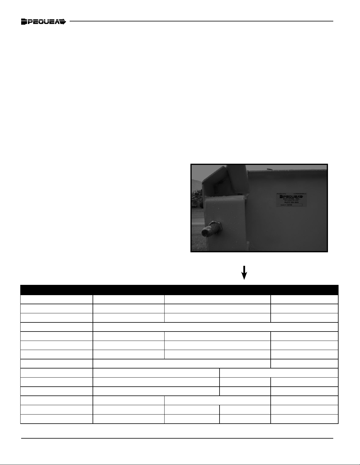
Skibo PEQUEA CX551 Manuale utente

Operator’s Manual
Wood Chipper
Model CX551
®®
THIS MANUAL MUST BE READ AND UNDERSTOOD BEFORE ANYONE OPERATES THIS MACHINE!
Manual# 990021
Revised 08/2015

YOU MUST FILL OUT YOUR WARRANTY REGISTRATION
TO ACTIVATE YOUR WARRANTY AND TO QUALIFY FOR
PARTS AND SERVICE!!
To the Owner;
Thank-You for choosing a quality product from Pequea Machine, Inc. We
strive to give you the best equipment and the best level of service of any
company. With a little care and maintenance this machine will do your work
for you for many years. In this manual, we make an effort to get you better
acquainted with the machine so you can achieve maximum performance. We
design and build all of our equipment with the end user in mind so we wel-
come any suggestions or ideas for improvement. Please note that it is within
our rights to make changes or improvements to our equipment without updat-
ing the equipment that was manufactured before the change took place.
Please take a few minutes to ll out the area below. This information will be
valuable to you when ordering parts or requesting service from your dealer.
Dealer Name:_____________________________
Dealer Phone Number:______________________
Service Manager/Technician:_________________
Model# and Description:_____________________
Serial Number:____________________________
Date of Purchase:__________________________

1
TABLE OF CONTENTS
Introduction ……………………………………………………………… 2
Intended Use ………………………………………………… 2
Serial Number …………………………………………….… 2
Specications ………………………………………………… 2
Safety …………………………………………………………………….… 3
Driveline Safety ……………………………………………… 4
Inspection and Setup …………………………………………………… 5
Operation …………………………………………………………………… 6
Startup ………………………………………………………… 6
Chipping Tips ………………………………………………… 6
Chip Chute Adjustments …………………………………… 7
Deector ………………………………………………………. 7
Feeding Material ……………………………………………… 8
Maintenance & Service ……………………………………………… 9
Belt Tension …………………………………………………… 9
Replacing the Belts …………………………………………… 9
Knives ………………………………………….……………… 10
Anvil …………………………………………………………… 10
Lubrication ...……………………………………………………………… 11
Bearings………………………………………..………………11
Feed Roller Slide …………………………………………….. 12
Warranty …………………………………………………………………… 13

2
Intended Use
Pequea Chippers are designed to chip natural, untreated wood only. Materials that are processed
may contain chemicals or biproducts that could corrode the machine, damage the blades, or sponta-
neously combust. Pequea will not cover under warranty any chipper that has been used for anything
besides natural wood.
Serial Number
The chipper’s serial number is located on the
inside of the base. This number helps us to track
changes and improvements and must be men-
tioned when ordering parts or requesting service.
For your convenience, a space has been provided
inside the front cover of this manual to record the
serial number, model number, purchase date, and
dealer name.
Specications
INTRODUCTION
Specications CX350 CX550 CX551 CX951
Chip Opening 3 x 5.5 in. (7.5 x 14cm) 5.5 x 8 in. (14 x 20cm) 9 x 16 in (23 x 40.6cm)
Drive System PTO PTO PTO
Engine N/A N/A N/A
Transport 3 Point Hitch
HP Required 16 35+ 80+
Rotor/Drum Size 65 lbs. 165 lbs. 490 lbs.
Knives (2) 2.5 x 3.25 x 5/16 in. (4) 2.5 x 3.25 x 5/16 in. (2) 4.5 x 9 x 5/8 in.
Knife Bolts 3/8” Recessed Head Hardened Bolts 5/8” Grade 8
Feed System Manual Hydraulic
Hydraulic Requirement N/A 6 GPM 8GPM
Feed Roller N/A 12” (30.5cm) 15.5” (39.4cm)
Hopper Opening 25 x 18 in. (62.5 x 45cm) 28 x 28 in. (70 x 70cm) 28 x 42 in (70 x 106cm)
Feed Height 38” (95cm) 41” (102.5cm) 21” (52.5cm) 29.5” (75cm)
Weight (lbs.) 375 650 775 2300

3
Do not operate this machine until this manual has been read and fully understood;
serious injury or death can occur if these safety warnings are ignored!
Never allow more than one person to operate this machine at a time. If two people are work-
ing together it will increase the chance of your workmate engaging the machine or causing
you to fall into the machine.
Wood is much harder than human esh! If your hand is ever near the chipping or feeding area
serious injury can occur. NEVER place your hands on the machine while it is chipping.
Never place your hands or feet on or near the machine while it is engaged.
Never place your hands or feet on or near the material while it is feeding.
DO NOT wear loose clothing, jewelry, or anything that can catch a branch that is feeding into
the chipper.
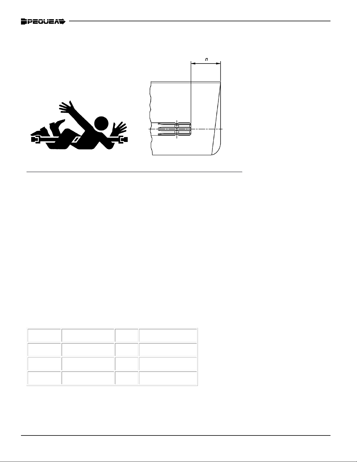
DO NOT stand directly in front of the infeed hopper when loading material into the hopper;
always load from the side of the hopper. This will not allow any part of your body to be pulled
into the machine.
Do not go near any hydraulic leaks. Hydraulic oil is under extreme pressure and a small leak
can easily penetrate the skin, causing serious injury and infection.
Always wear hearing protection, eyewear, gloves, and long pants when operating the chip-
per.
Never place your hands beyond the opening of the hopper while the chipper is running.
Never allow children, disabled, or untrained persons to operate the chipper.
Do not operate the chipper near bystanders, public roads, or anywhere that the debris may
travel far enough to injure another person.
Never move the chipper while it is running
Shut off the tractor and allow the chipper to come to a complete stop before removing any
debris.
Never perform any maintenance or repair while the chipper is running.
SAFETY

4
Stay Clear of Rotating Drivelines
TS1644-UN-22AUG95 H96219-UN-29APR10
Entanglement in rotating driveline can cause serious injury or death.
Keep tractor master shield and driveline shields in place at all times. Make
sure rotating shields turn freely.
Wear close fitting clothing. Stop the engine and be sure that PTO driveline
is stopped before making adjustments, connections, or cleaning out PTO
driven equipment.
Do not install any adapter device between the tractor and the primary
implement PTO drive shaft that will allow a 1000 rpm tractor shaft to power
a 540 rpm implement at speeds higher than 540 rpm.
Do not install any adapter device that results in a portion of the rotating
implement shaft, tractor shaft, or the adapter to be unguarded. The tractor
master shield shall overlap the end of the splined shaft and the added adaptor
device as outlined in the table.
PTO Type
Diameter Splines
n ± 5 mm (0.20 in.)
1 35 mm (1.378
in.)
6 85 mm (3.35 in.)
2
35 mm (1.378 in.)
21 85 mm (3.35 in.)
3
45 mm (1.772 in.)
20 100 mm (4.00 in.)

5
INSPECTION AND SET-UP
• Follow the instructions in the lubrication section of this manual to make sure the chipper is
greased properly. The initial grease is applied at the factory, but a routine maintenance sched-
ule is the user’s responsibility.
• Check all bolts and nuts to make sure everything is tight. All hardware is checked at the fac-
tory, but sometimes it will vibrate loose during shipment. Also check all fasteners periodically
between uses. A wood chipper produces high vibration levels which can cause hardware to
loosen.
• Check the position of the knives in relation to the chip anvil. The recommended setting is 1/32”
between the anvil and the closest knife. You may notice the rotor has a slight wobble which
will cause some of the knives to run closer than others. This is normal. See page 9 for instruc-
tions on adjusting the anvil
• Check the length of the PTO shaft. Some tractor 3-point hitch arms are shorter and require a
shorter PTO shaft. To determine whether your shaft needs to be cut down to t you will need
to connect the 3-point arms to the chipper, connect the PTO shaft to both the tractor and chip-
per, and slowly raise the 3-point hitch. Watch closely to make sure that the PTO shaft does not
fully retract. If it does, you will need to remove it and cut it down accordingly. If the PTO shaft
is not tted properly it can “bottom out” and cause damage to the PTO shaft or the chipper.
• Check the chip chute locking device to make sure it locks the chute securely into position
when the handle is in the locked position. This adjustment is also made at the factory but
needs to be readjusted after the chute is “worn in”.

6
Startup
Chipping Tips
• Feed the blunt end of the branch in rst.
• Trim the side limbs that won’t t into the hopper before you feed the chipper.
• Feed the material into the hopper from the side of hopper so that debris doesn’t y back at
you. Never stand directly in front of the hopper when feeding the chipper.
• If you have a lot of dry material try to mix in some green (fresh) limbs with the dry. The mois-
ture in the green wood will lubricate and cool the knives. Chipping only dry wood will cause
the knives to heat up. A hot knife will lose its edge much quicker.
• Place tractor transmission in neutral and set the parking brake, then turn the tractor engine
off.
• Connect the 3pt. hitch linkages to the chipper and secure them with safety snap pins.
• Adjust the top link so that the chipper sits level.
• Connect the pto shaft to the tractor. Be sure that the balls are set in the ball groove of the
tractor pto shaft. Make sure that the pto safety chains are attached to both the tractor and
the chipper to keep the protective PTO shield from rotating.
• Make sure the feed drive control bar on the chipper is in the ‘neutral’ position and connect
the hydraulic hoses to the tractor.
• Start tractor engine and hold the engine rpm’s at a strong idle. Engage the pto slowly. If the
tractor is running at a high speed when you engage the PTO you could damage the drive
belts or break the shear bolt on the PTO shaft. After the rotor is spinning freely increase the
tractor rpm’s until the pto speed is around 540 rpm’s and engage the hydraulics.
• With the chipper now running at full speed you may begin chipping. Start by feeding small
diameter branches until you get better acquainted with the machine and its operation, then
you may begin feeding larger pieces.
OPERATION

7
OPERATION
Chip chute adjustments
To position the chip chute, pull the spring loaded pin (Figure 2) upward and rotate it to lock it
the retracted position (Figure 3). The chute conveniently rotates a full 360 degrees. Rotate it
to the desired position. Pull the pin upward again and rotate it until it can fully extend and the
chute can know longer rotate freely. Be sure the pin is locked in place, fully extended, before
transporting or the chipper!
Figure 2
Pull up to
rotate chute
Figure 3
Figure 3
Deector
The chip deector easily adjusts to regulate the distance that the chips are thrown. Loosen the
two clamp knobs and adjust as desired. (Figure 3 & 4)
Figure 4
Pull up and rotate
to lock or release

8
The ow control valve (Figure 5) will control the speed of the material being fed into the chipper.
The tractor’s hydraulic pressure and will also contribute to the speed of the feed.
To adjust the speed of the feed system, nd a small branch and feed it into the chipper at with the
feed adjusted to 3 or 4 and keep adjusting up until the chips are 3/8 to 1/2 inch thick. The feed set-
ting “0” will completely stop the ow of oil to the motor, stopping the feed roller
The hydraulic system on the chipper requires at least 6 GPM to operate the chipper at full capac-
ity. If the tractor has too much ow the oil in the tractor could overheat, causing the hydraulic uid
to lose it’s viscosity. In this situation a self contained hydraulic kit should be installed. This option is
available from Pequea. Contact your local dealer/distributor for pricing and availability.
Sometimes when the brush is wet or if there are a lot of small twigs and branches the feed roller
can slip because of the wet wood or of the small sized material. In this situation it is best to grab the
control bar and switch from forward to reverse several times. You can even reverse the material and
rotate it a different way so that the roller grabs a different part of the branch.
OPERATION
Feeding Material
Shown above (Figure 6) is the control bar that operates the feed roller. This control bar has
three positions, forward, neutral, & reverse. The feeding position is to the rear of the machine so
that in an emergency the operator can just push the control bar and it will either stop or reverse
the feed roller. Always keep the control bar in the neutral position whenever you are not feeding
the chipper to eliminate the chance of accidently feeding something into the machine.
010
Figure 5
Hydraulic Flow Control Forward Neutral Reverse
Figure 6
Indice
Altri manuali Skibo Cippatrice


