Slamtec A2M4 Manuale utente
www.slamtec.com
Shanghai Slamtec.Co.,Ltd
RPLIDAR A2
Low Cost 360 Degree Laser Range Scanner
Development Kit User Manual
Model: A2M4
2016-08-17 rev.1.0

CONTENTS ...................................................................................................................................................1
OVERVIEW ...................................................................................................................................................3
ITEMS IN THE DEVELOPMENT KIT .......................................................................................................................3
RPLIDAR A2..................................................................................................................................................... 4
USB ADAPTER....................................................................................................................................................4
CONNECTION AND USAGE .....................................................................................................................5
CONNECTION .....................................................................................................................................................5
INSTALL DRIVER FOR THE USB ADAPTER........................................................................................................... 6
RUN DEMO APPLICATION .................................................................................................................................. 7
TROUBLESHOOTING.......................................................................................................................................... 10
MOTOR SPEED ADJUSTMENT........................................................................................................................... 10
SDK INTRODUCTION AND USAGE......................................................................................................11
RPLIDAR A2 PIN DEFINITION AND SPECIFICATION ....................................................................................... 11
PIN DEFINITION FOR THE USB ADAPTER......................................................................................................... 12
CONFIGURE RPLIDAR A2 SCAN FREQUENCY................................................................................................. 12
SDK USAGE...................................................................................................................................................... 12
OPERATION RECOMMENDATION....................................................................................................... 13
PRE-HEATING FOR BEST PERFORMANCE .........................................................................................................13
AMBIENT TEMPERATURE...................................................................................................................................13
AMBIENT LIGHT................................................................................................................................................ 13
REVISION HISTORY ................................................................................................................................. 14
APPENDIX .................................................................................................................................................. 15
IMAGE AND TABLE INDEX ................................................................................................................................. 15
Contents
3/ 15
Copyright (c) 2009-2013 RoboPeak Team
Copyright (c) 2013-2016 Shanghai Slamtec Co., Ltd.
RPLIDAR A2 development kit includes the matched tools used for evaluating
RPLIDAR’s performance and initial development. After connecting the RPLIDAR
A2 with PC via USB cable and adapter, Users can observe the cloud map of the
environment scanning point collected by the RPLIDAR and start development
based on the SDK.
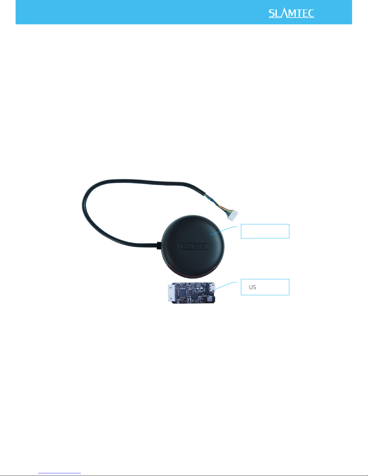
Items in the Development Kit
RPLIDAR Development Kit contains:
oRPLIDAR(PWM motor driver embedded)
oUSB Adapter
Figure 1-1 Items in the RPLIDAR Development Kit
Overview
RPLIDAR
USB Adapter
4/ 15
Copyright (c) 2009-2013 RoboPeak Team
Copyright (c) 2013-2016 Shanghai Slamtec Co., Ltd.
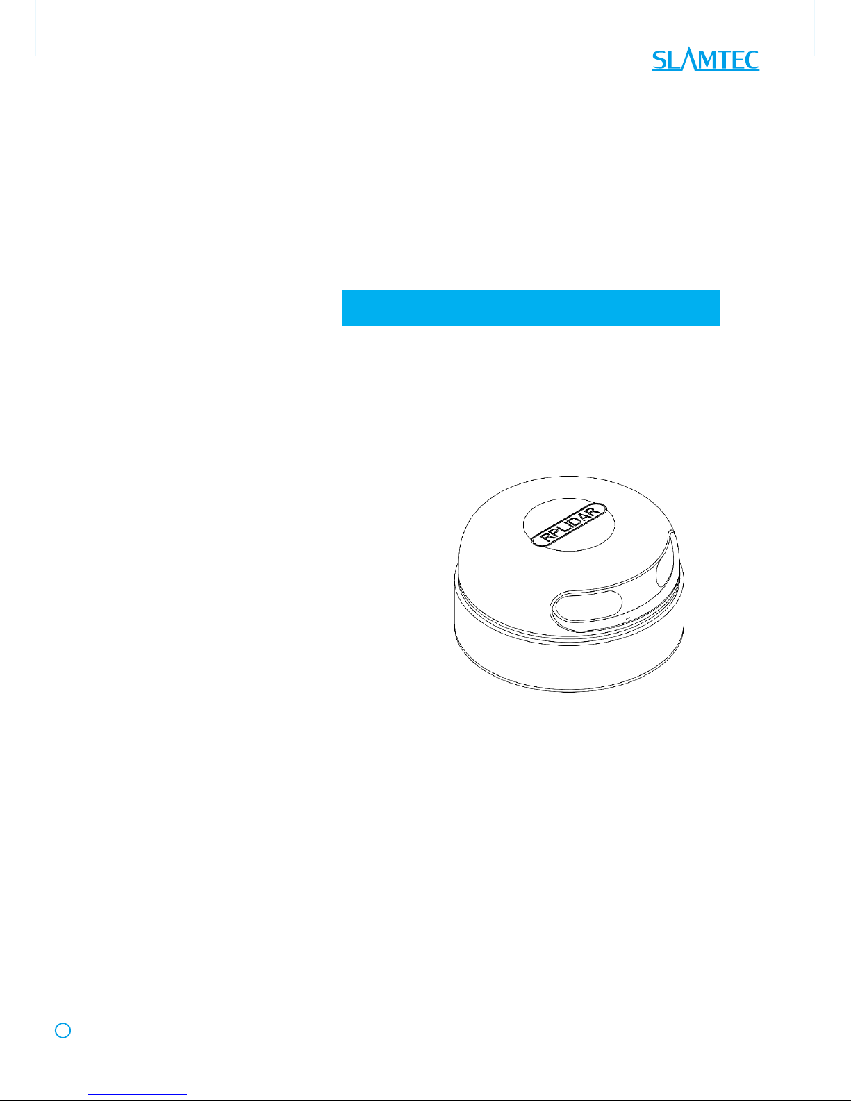
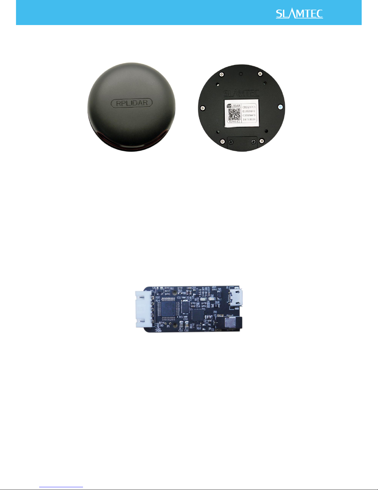
RPLIDAR A2
Figure 1-2 The RPLIDAR
The RPLIDAR A2 development kit contains standard RPLIDAR A2 unit (A2M4-R1).
The RPLIDAR is embedded with logic IO drivable motor controller which can be
used to configure the scan frequency by tuning motor speed. Developers can also
choose to turn off the motor for power saving purpose.
RPLIDAR usage and interface definition will be introduced in the coming sections.
USB Adapter
Figure 1-3 RPLIDAR Adapter
5/ 15
Copyright (c) 2009-2013 RoboPeak Team
Copyright (c) 2013-2016 Shanghai Slamtec Co., Ltd.
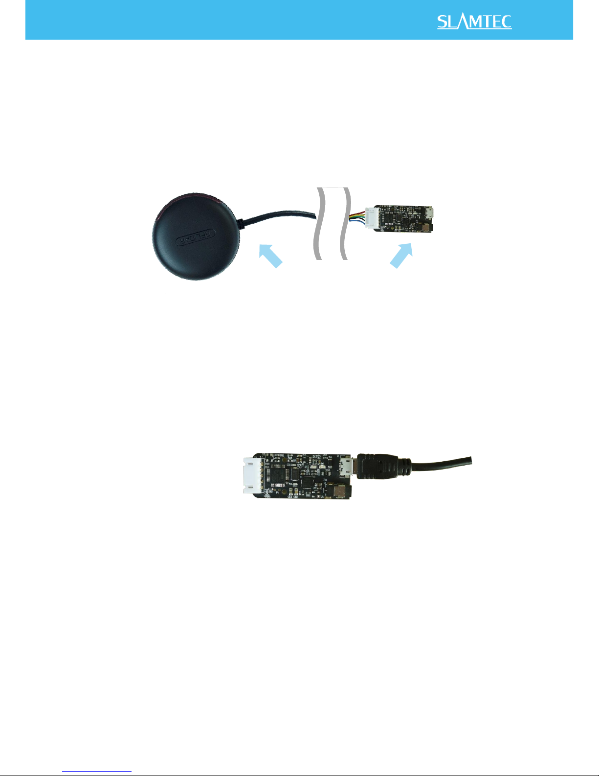
Connection
RPLIDAR A2 can be easily connected to PC according to the following steps.
1) Connect RPLIDAR A2 with the USB adapter.
Figure 2-1 Connect RPLIDAR A2 and USB Adapter
2) Connect the USB adapter to your PC via the Micro-USB cable. If the PC is
on, after connecting the USB cable to your PC, the indicator light of the USB
will light up but the RPLIDAR will not start scanning.
Figure 2-2 Connect the USB Adapter to PC via Micro-USB Cable
Connection and Usage
6/ 15
Copyright (c) 2009-2013 RoboPeak Team
Copyright (c) 2013-2016 Shanghai Slamtec Co., Ltd.
Install Driver for the USB Adapter
The USB adapter converts UART to USB by using CP2102 chip. You need to install
the device driver for the chip. The driver can be found in the provided SDK
package or downloaded from Silicon Labs’official website:
http://www.silabs.com/products/interface/usb-bridges/Pages/usb-bridges.aspx
Here’s the installation steps in Windows:
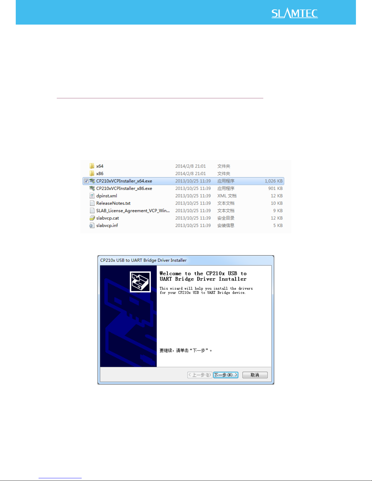
After connecting the RPLIDAR with PC, please find the driver file “CP210x VCP
Windows” and choose correct operating system version accordingly: x86 for 32-
bit OS and x64 for 64-bit OS.
Figure 2-3 Choose USB Adapter Driver for Installation
Figure 2-4 Start Page of USB Adapter Driver Installation
7/ 15
Copyright (c) 2009-2013 RoboPeak Team
Copyright (c) 2013-2016 Shanghai Slamtec Co., Ltd.
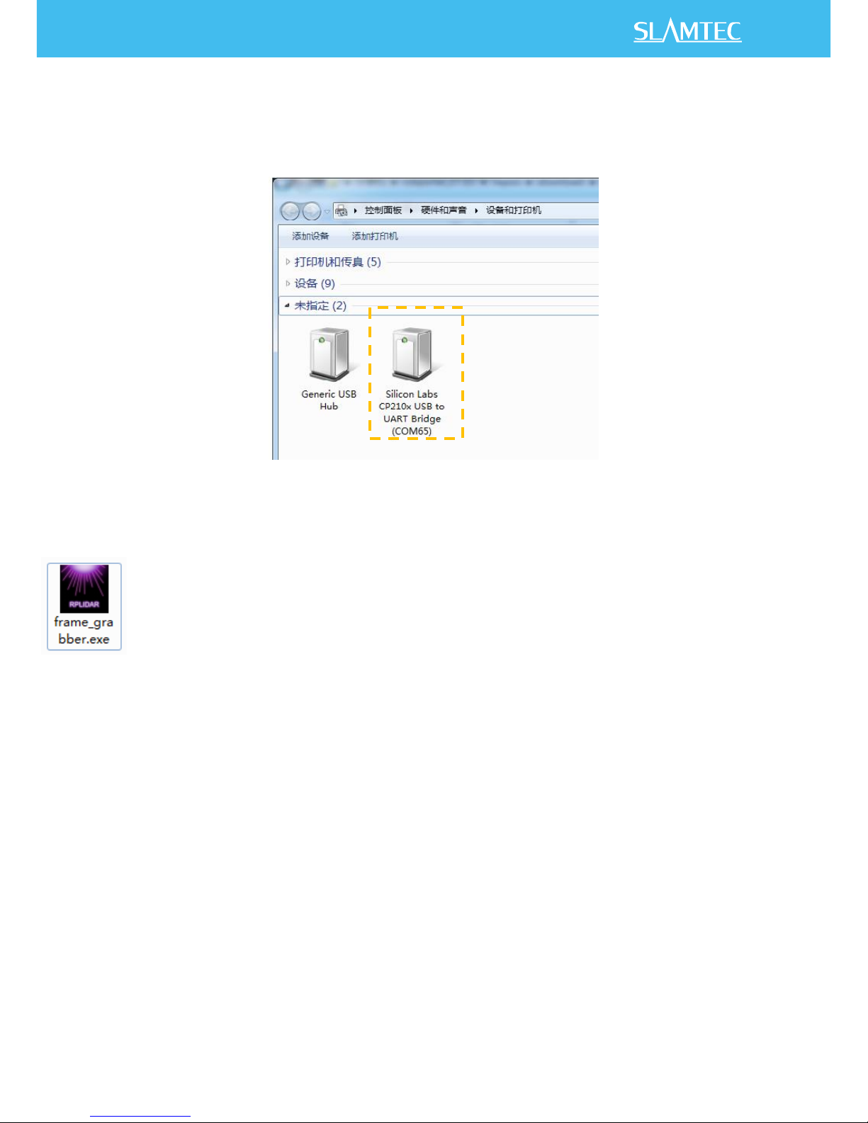
After Installing the driver according to the above installation steps, you will see
corresponding serial port name in the [Control Panel] -> [Device and Printers].
Please refer to the below figure.
Figure 2-5 Recognized Serial Port Name Matched with the USB Adapter
Run Demo Application
Frame_grabber is a GUI demo application provided by SLAMTEC. You can view
the scan result directly in the UI and save the scan result to files for further
processing. The source code of this demo application is also provided in matched
SDK for reference.
This GUI demo can only run under Windows. For Linux and MacOS users, please
refer to the other simple demo provided in the SDK.
Please make sure you have connected RPLIDAR to PC by using USB adapter and
installed the device driver correctly before running the demo application.
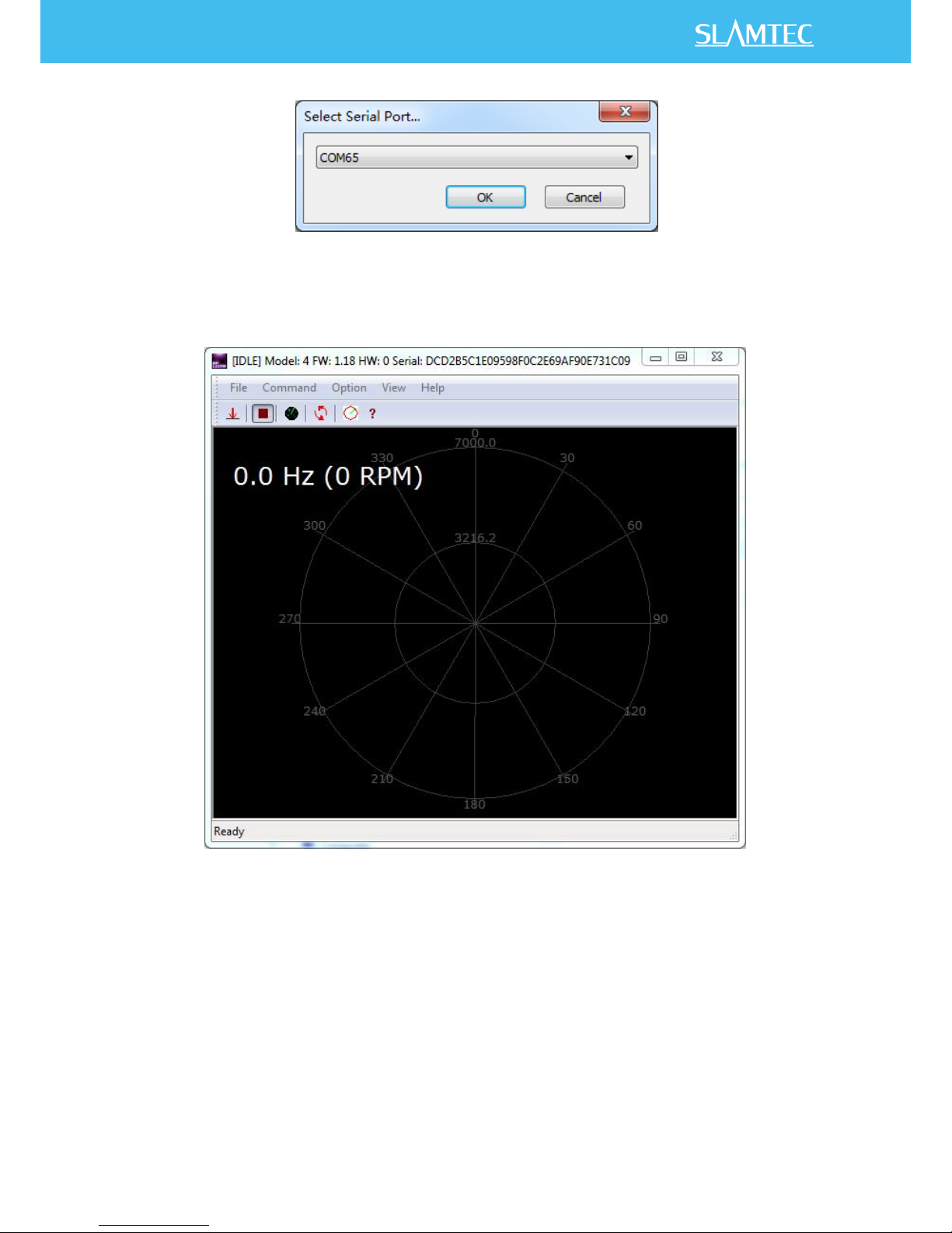
Starting demo application framgrabber.exe and choose serial port name identified
in the previous step.
8/ 15
Copyright (c) 2009-2013 RoboPeak Team
Copyright (c) 2013-2016 Shanghai Slamtec Co., Ltd.
Figure 2-6 Choose Serial Port Name Matched with the USB Adapter
If the connection is ok, you shall see the UI like this:
Figure 2-7 The Start of Demo Application
The firmware/hardware version and serial number of the RPLIDAR will show in the
title line of the GUI. The supported commands of RPLIDAR are showed in the tool
bar. The descriptions are listed in the bellow table.
9/ 15
Copyright (c) 2009-2013 RoboPeak Team
Copyright (c) 2013-2016 Shanghai Slamtec Co., Ltd.
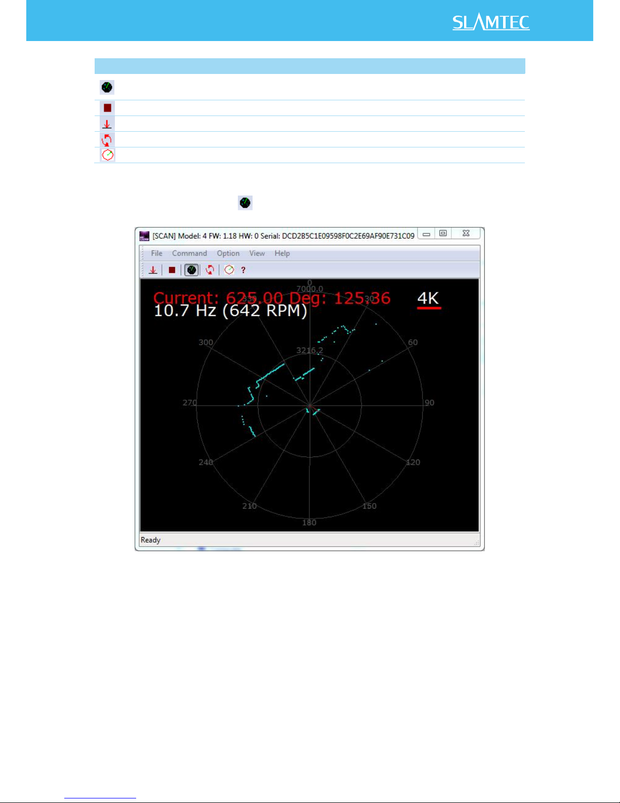
Figure 2-8 The Supported Commands in Demo Application
Press the Start Scan button ,the scan data will be displayed in the UI as below:
Figure 2-9 The Scan Outline in RPLIDAR Demo Application
Use the mouse wheel to zoom in and out. Move the cursor to any sample point,
the distance and degree value to the RPLIDAR will be showed in the screen with
red font.
The scan frequency is also showed in the UI.
Button
Function
Description
Start Scan
Scan data will be displayed after scan core starting work
Stop Scan
Scan core enter power save mode
Save Scan Data
Save current scan data to the local file
Restart RPLIDAR
Restart scan core to clear internal errors
Adjust Motor Speed
Adjust the motor speed as required
10 / 15
Copyright (c) 2009-2013 RoboPeak Team
Copyright (c) 2013-2016 Shanghai Slamtec Co., Ltd.
Troubleshooting
When the scan core or the laser power works abnormally, the scan core will enter
protection mode. This state can be retrieved by using SDK API. If such scenario
happened, please send restart command to reset the scan core.
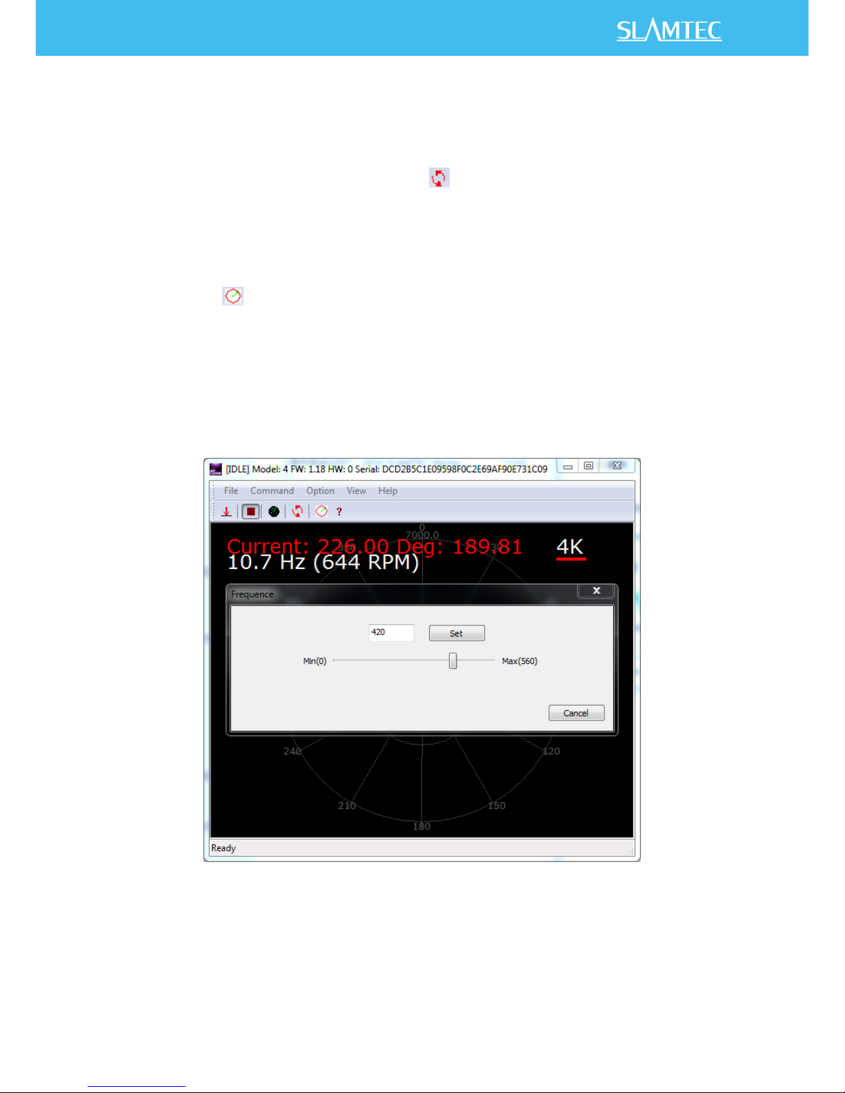
Motor Speed Adjustment
During the running process, different motor rotating speed can be achieved by
pressing the button. There will be a speed adjustment dialog box popped up
for users to enter required speed. After clicking set, the motor will work as the
settled rotating speed automatically. User can also drag the progress bar to the
required rotating speed.
The current rotating speed will show in rea time in the Framegrabber main
dialogue box.
Figure 2-10 The Motor Speed Adjustment Dialogue
Indice
Altri manuali Slamtec Scanner


