Smartrise CEDES Manuale utente


Page intentionally left blank

CEDES APS Landing System
June 24, 2021 ©2021 Smartrise Engineering, Inc. All Rights Reserved Page i
Document History
Date
Version
Summary of Changes
June 24, 2021
3.0
Updated the CEDED APS Landing information due to new
bracket
Deleted test procedures
June 13, 2020
2.7
Changed cover page
New document format
Updated references
Added additional figures for clarity
August 23, 2018
2.6
Added minimum SRU version software to perform tests
Updated all testing procedures
Added extra byte 2 to troubleshooting
July 2, 2018
2.5
Updated header and footer
June 19, 2018
2.4
Updated cover page
June 19, 2018
2.3
Updated Upper Tape Mount Assembly positioning
Added ETS Switch Positioning table
Specified NTS Learning for traction only
Added 150 fpm or slower for hydraulic and traction type
after learning the hoistway
Marcy 27, 2018
2.2
Updated figure numbers
January 29, 2018
2.1
Initial release

CEDES APS Landing System
Page ii © 2021 Smartrise Engineering, Inc. All Rights Reserved June 24, 2021
Page intentionally left blank

CEDES APS Landing System
June 24, 2021 ©2021 Smartrise Engineering, Inc. All Rights Reserved Page iii
Table of Contents
1CEDES APS Landing System ............................................................................1
1.1 Coded Tape.................................................................................................................. 1
1.2 Sensor Assembly Installation ........................................................................................ 3
1.3 Upper Tape Mount Assembly ....................................................................................... 5
1.4 Tape Clip Assembly....................................................................................................... 7
1.5 Lower Tape Mount Assembly ......................................................................................11
1.6 Sensor Array Assembly ................................................................................................12
1.7 Emergency Tape Break (ETB) Switch Assembly ............................................................17
1.8 Fine Tune ....................................................................................................................18
1.9 Alignment ...................................................................................................................20
2Learning the Hoistway..................................................................................21
3Slow Down...................................................................................................22
3.1 Setting Up Emergency Terminal Slowdown..................................................................22
3.2 Setting Up Terminal Slowdown Reducing Device .........................................................23

CEDES APS Landing System
Page iv © 2021 Smartrise Engineering, Inc. All Rights Reserved June 24, 2021
List of Figures
Figure 1: Coded Tape.....................................................................................................................................................1
Figure 2: Gloves Required..............................................................................................................................................1
Figure 3: Tape Minimum Bend Radius...........................................................................................................................2
Figure 4: Routing Tape...................................................................................................................................................2
Figure 5: Unistrut Installation........................................................................................................................................3
Figure 6: Sensor Array Assembly Positioning ................................................................................................................4
Figure 7: Location of Tape Mount Assemblies...............................................................................................................5
Figure 8: Upper Tape Unistrut Installation ....................................................................................................................6
Figure 9: Hardware ........................................................................................................................................................6
Figure 10: Gap Verification ............................................................................................................................................7
Figure 11: Tape Clip Assembly .......................................................................................................................................7
Figure 12: Tape Clip Insertion........................................................................................................................................8
Figure 13: Tape Clip Assembly Alignment .....................................................................................................................8
Figure 14: Optical Axis ...................................................................................................................................................9
Figure 15: Tape Clip Assembly Placement (Rear View) .................................................................................................9
Figure 16: Tape Clip Assembly Alignment ...................................................................................................................10
Figure 17: Lower Tape Mount Assembly .....................................................................................................................11
Figure 18: Hardware to Lower Tape Mount Assembly................................................................................................11
Figure 19: Sensor Array Assembly ...............................................................................................................................12
Figure 20: Sensor Array Assembly Connected to C-Channel (Right Side)....................................................................13
Figure 21: Sensor Array Assembly Connected to C-Channel (Left Side) ......................................................................13
Figure 22: Sensor Array Assembly (Right Side)............................................................................................................14
Figure 23: Sensor Array Assembly (Left Side) ..............................................................................................................15
Figure 24: Dual Sensor Array Assembly.......................................................................................................................15
Figure 25: Dual Sensor Array Assembly (Right Side)....................................................................................................16
Figure 26: Dual Sensor Array Assembly (Left Side)......................................................................................................17
Figure 27: Emergency Tape Break Switch in Series with Buffer Switch.......................................................................17
Figure 28: Unistrut to Lower Tape Mount Assembly...................................................................................................18
Figure 29: Emergency Tape Break Switch....................................................................................................................18
Figure 30: Sensor Array Assembly Adjustment ...........................................................................................................19
Figure 31: CAT5 Camera to CIB Board .........................................................................................................................19
Figure 32: Optical Sensor LEDs ....................................................................................................................................20
Figure 33: Alignment Arrows.......................................................................................................................................20
Figure 34: Stopping Points...........................................................................................................................................21

CEDES APS Landing System
June 24, 2021 ©2021 Smartrise Engineering, Inc. All Rights Reserved Page v
List of Tables
Table 1: ETS Positions ..................................................................................................................................................22
Table 2: TSRD Positions ...............................................................................................................................................23

CEDES APS Landing System
Page vi © 2021 Smartrise Engineering, Inc. All Rights Reserved June 24, 2021
Page intentionally left blank

CEDES APS Landing System
June 24, 2021 ©2021 Smartrise Engineering, Inc. All Rights Reserved Page 1
1CEDES APS Landing System
The CEDES Absolute Positioning System (APS) consists of:
•Coded Tape
•Sensor Array Assembly
•Tape Clip Assembly
•Top Tape Mount Assembly
•Bottom Tape Mount Assembly
•Emergency Tape Break Switch Assembly
1.1 Coded Tape
The tape is a special coded tape that provides the absolute positioning feedback to the CEDES
camera.
Figure 1: Coded Tape
WARNING
THE TAPE EDGE IS SHARP. CUT-PROOF GLOVES MUST BE WORN WHILE HANDLING THE TAPE.
Figure 2: Gloves Required
CEDES APS Landing System
Page 2 © 2021 Smartrise Engineering, Inc. All Rights Reserved June 24, 2021
The following procedure describes how to install the tape.
1. Open the tape box at the top corner, being mindful of the sharp end or edges, and pull
out tape as needed.
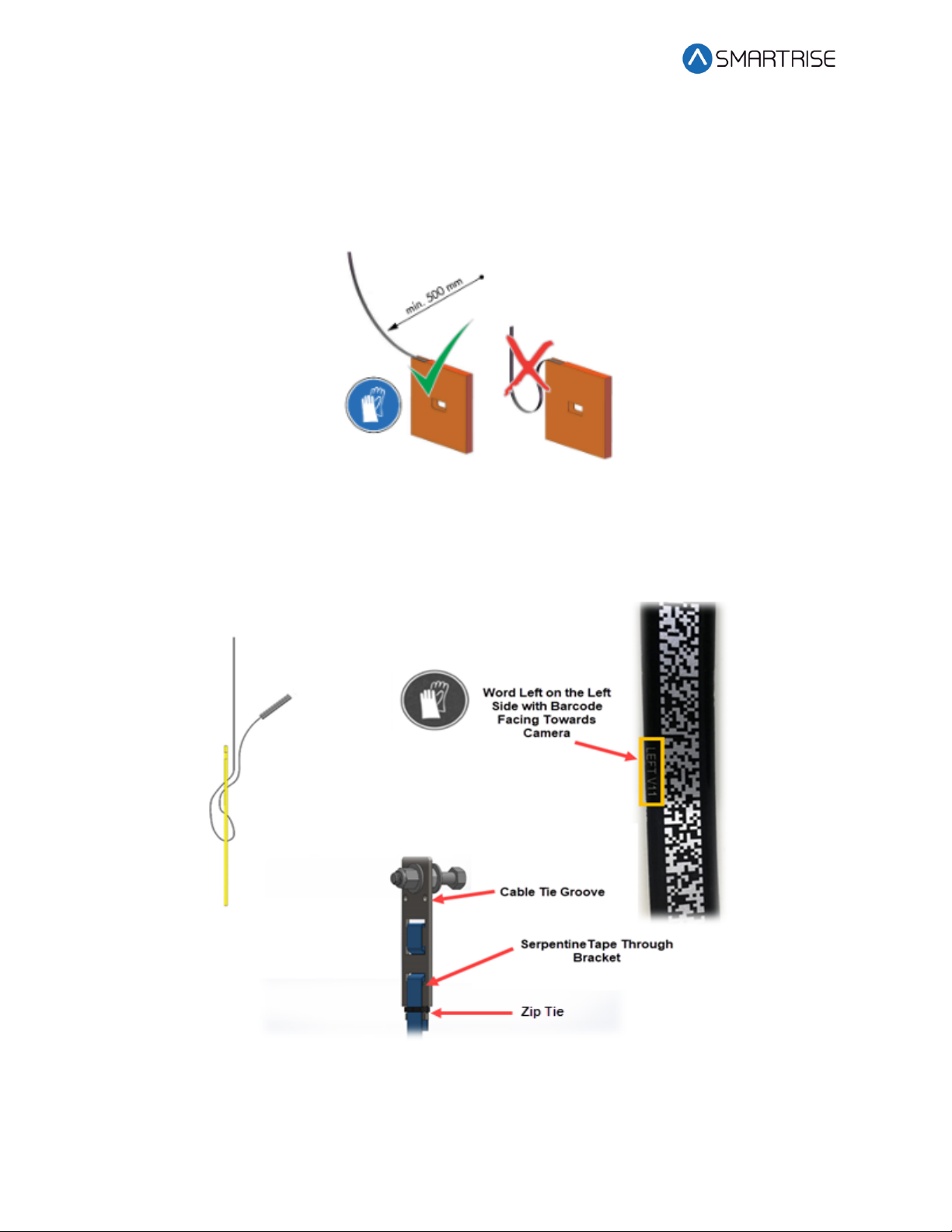
CAUTION: Do not pull too much tape out of the box as excessive bending can occur and
damage the tape.
Figure 3: Tape Minimum Bend Radius
2. Serpentine and secure the tape through the bracket then zip tie loose end.
NOTE: Verify the words Left are on the left side of the tape with the barcode facing out
towards the camera.
Figure 4: Routing Tape
Indice
Altri manuali Smartrise Hardware per computer

Manuali Hardware per computer popolari di altre marche

EMC2
EMC2 VNX Series Manuale del proprietario

Panasonic
Panasonic DV0PM20105 Manuale utente

Mitsubishi Electric
Mitsubishi Electric Q81BD-J61BT11 Manuale utente

Gigabyte
Gigabyte B660M DS3H AX DDR4 Manuale utente

Raidon
Raidon iT2300 Manuale utente

National Instruments
National Instruments PXI-8186 Manuale utente


