Sodi RS3 KZ DD2 Istruzioni operative

MAN_Sigma_EN_02
USER AND MAINTENANCE MANUAL
EN

THIS DOCUMENT CAN NOT BE REPRODUCED OR RELEASED WITHOUT THE SODIKART AUTHORISATION.
10/2022
2EN
USER AND MAINTENANCE MANUAL
Foreword
This document is based on the most recent specications at the time of publication. Sodikart nevertheless reserves
the right to apply changes in order to uphold its policy of continuous improvement of its products. If modications have
been made in the meantime, there may be certain dierences between the content of the user guide and the go-kart
you own.
The document applies to all Sodikart models and includes descriptions and explanations concerning both the standard
and optional equipment. This means that this manual might contain some sections that do not apply to your go-kart
model. The illustrations are used to describe the principles of assembly. They are not intended to be an exact, detailed
representation of the go-kart.
If you have problems or questions about your go-kart, please contact your local distributor or representative of
Sodikart.
© Sodikart 2022.
Parc d’activités des Hauts de Couëron
B.P.60 - 44220 COUËRON - France
Tel. : (33) 02 40 38 26 20
Fax : (33) 02 40 38 26 21

MAN_Sigma_EN_02
USER AND MAINTENANCE MANUAL
3
EN
1 - General ................................................. 4
1.1 - Warning ................................................................... 4
1.2 - General precautions................................................ 4
1.3 - Safety instructions.................................................. 4
1.3.1 - Meaning of the ags............................................5
1.3.2 - Safety stickers......................................................5
2 - Reception ............................................. 6
2.1 - Main components................................................... 6
2.2 - Tooling for assembly and adjustment .................. 7
2.3 - Maintenance products............................................ 7
3 - Assembly.............................................. 8
3.1 - Precautions and recommendations ...................... 8
3.2 - Frame stabilizers .................................................... 8
3.3 - Positioning of the safety brake cable.................... 8
3.4 - Assembly of the fuel tank and of the
overow bottle....................................................... 9
3.5 - Assembly of the steering column and
steering wheel ....................................................... 9
3.6 - Assembly of the seat............................................ 10
3.7 - Assembly of the seat stiffeners........................... 11
3.8 - Assembly of the bodywork................................... 12
3.9 - Mounting the rear protections ............................. 14
4 - Commissioning..................................15
4.1 - Safety instructions to the pilots........................... 15
4.2 - Pilot protection...................................................... 15
5 - Adjustments.......................................16
5.1 - Standard adjustments.......................................... 16
5.2 - Adjustment of front wheels.................................. 18
5.2.1 - Adjustment of front tracking width...................18
5.2.2 - Adjustment of front wheel height .....................18
5.2.3 - Adjustment of the caster...................................19
5.2.4 - Adjustment of the camber.................................20
5.2.5 - Quick adjustment of caster/camber pill...........21
5.2.6 - Front wheel alignment.......................................22
5.2.7 - Adjustment of tie rods.......................................22
5.3 - Adjustment of rear wheels................................... 23
5.3.1 - Adjustment of hub .............................................23
5.3.2 - Position of rear axle...........................................23
5.3.3 - Type of axle ........................................................23
5.3.4 - Tightening torque for rear axle bearing ............24
5.4 - Adjustment of seat ............................................... 24
5.5 - Adjustment of the brake distributor..................... 24
5.5.1 - Standard adjustment .........................................24
5.5.2 - More braking power on the front brakes ..........24
5.5.3 - More braking power on the rear brakes............24
6 - Maintenance ......................................25
6.1 - Brakes - Usual maintenance................................. 25
6.1.1 - Fluids and lubricants .........................................25
6.1.2 - Frequency of cleaning and maintenance .........25
6.1.3 - Replacing brake pads on the D18
4-pistons callipers (front)..................................26
6.1.4 - Replacing brake pads on the D20
4-pistons callipers (rear)...................................26
6.1.5 - Replacing brake pads on the D28
2-pistons callipers (rear)...................................27
6.1.6 - Adjusting the gap between the pads and
the disc...............................................................27
6.1.7 - Replacing the brake hose ..................................27
6.1.8 - Tightness of the brake hose screew.................28
6.1.9 - Bleeding the front brake circuit.........................28
6.1.10 - Bleeding the rear brake circuit ........................29
6.1.11 - Cleaning............................................................30
6.2 - Brakes - Workshop maintenance......................... 30
6.2.1 - Replacing calliper seals / 4 pistons
calliper D18 (front) ............................................30
6.2.2 - Replacing calliper seals / 4 pistons
calliper pistons D20 (rear) ................................32
6.2.3 - Replacing calliper seals / 2 pistons
calliper D28 (rear)..............................................34
6.2.4 - Replacing master cylinder seals and pistons 35
6.3 - Tyres ...................................................................... 37
6.3.1 - Tyres change......................................................37
6.4 - Cleaning the chassis ............................................ 38
6.5 - Maintenance summary......................................... 38
6.5.1 - Bolting.................................................................38
6.5.2 - Steering...............................................................38
6.5.3 - Bodywork parts ..................................................38
6.5.4 - Tyres ...................................................................38
6.5.5 - Braking................................................................38
7 - Troubleshooting.................................39
7.1 - The kart will not brake .......................................... 39
7.2 - The kart brakes continually.................................. 39
7.3 - The kart is hard to turn ......................................... 39
7.4 - The steering of the kart is not precise................. 39
7.5 - The kart tends to go to the side........................... 39
7.6 - The kart skids very much on bends..................... 39
8 - Index ...................................................40
9 - Homologation ....................................41
Table of contents
10/2022
4EN
USER AND MAINTENANCE MANUAL
1 - General
1.1 - Warning
A go-kart can be dangerous if not maintained or used
correctly. Read carefully this manual and pay a particular
attention to safety warnings and notes.
● Not following the safety instructions of this manual, may
involve your liability if an accident occurs.
● Read carefully hints, instructions or warnings following a
notes or warnings:
►Indicates a strong possibility of serious
personal injury or death if instructions are
not followed.
●Indicates a risk of property damage if
instructions are not followed.
●Provides useful information.
● The warnings and precautions contained in this
manual cannot cover every possible risk related to the
maintenance, or lack of maintenance, of a go-kart.
● In addition to the messages given, it is important to apply
good judgement and the basic principles of mechanical
safety.
● In case of any doubt on the way a particular operation of
maintenance must be made, ask for advice from a more
experienced mechanic.
1.2 - General precautions
● Keep the go-kart in its original state.
● Do not modify the go-kart.
● Use original SODIKART parts only.
● For the safety and reliability of the go-kart, it is important
to carry out the appropriate maintenance and repairs.
● If toxic or ammable products are used, make sure that
the places are ventilated well and that all the instructions
of the manufacturer of these products are respected.
● Never use petrol as a substitute for cleaning solvent.
● Check all hoses and mountings in the brake system to
ensure that there are no leaks.
● Ensure that the safety stickers are present and in good
condition.
● Put in order the parts that must be reused, to be able to
reassemble them in the correct manner.
● Use adapted or special tools for every operation if
specied.
● Before reassembly, make sure parts are clean. Apply
grease if needed.
● Use only lubricants, glues or specied waterproof
products.
● Replace by new parts: O-rings, self locking nuts,
split pins, circlips, and other specic parts after every
disassembly.
● Clean the contact areas from any trace of material,
before reassembling the parts.
● Tighten up all xations bolts to the specied tightening
torque using a torque wrench.
● Remove any trace of oil or grease from all threads.
● Check the correct tightening of all parts and their
functionality after reassembly.
● To protect the environment, comply with all legal
requirements for the disposal of used uids, batteries,
and tyres.
● To protect nature and the environment, dispose of used
parts in accordance with regulations.
1.3 - Safety instructions
The kart has been designed in accordance with the pending
rules of the CIK-FIA in force, which ensures an optimum
safety in normal conditions of use.
Its high speed and performances imply a proper
maintenance.
For your safety and the one of other pilots, please thoroughly
respect:
● The assembly instructions.
● The adjustment recommendations.
● The maintenance plan.
►The SODI chassis is designed for safety
and reliability in normal conditions of use.
Before using it, please read this manual
and carefully follow the instructions. By not
doing so, you might be exposed to a risk of
severe, even fatal injury, and your kart might
suer damages.
►The SODI chassis can only be used on an
approved track and by a driver who is in
possession of a valid membership card of
the kart’s federation of his own country.
►Prior to going on the track, please check all
points related to safety.
►In order to avoid re, put the kart at least one
meter away from the buildings. Never leave
inammable objects close to the kart.
►If fuel has been poured, wipe and wait for
vapours to dissipate, before starting the kart.
►Kids and domestic animals have to be kept
away from the kart and the track.
►Never let anybody use the kart without
making sure before that the driver has
knowledge of all the safety instructions and
that he wears the adequate protections.
►Driving prohibited for any pilot with health
problems (for example: heart problems).
►Driving prohibited for any pilot having a
strange behavior or being under drugs or
alcohol inuence.
MAN_Sigma_EN_02
USER AND MAINTENANCE MANUAL
5
EN
1.3.1 - Meaning of the ags
Green ag
Do not apply the throttle before this ag is
out.
Black ag
Driver is to proceed to the pit lane
immediately, wait for sta instructions.
Blue ag
A faster driver is behind you.
Move o the ideal driving line.
Yellow ag
There is a dangerous situation ahead.
Ease o the throttle and do not pass.
This ag will be used in combination with
the warning lights along the track.
Red ag
Trouble on the track - drive slowly.
Drive to pit lane immediately.
Checkered ag
The driving session is nished.
Enter the pit lane slowly.
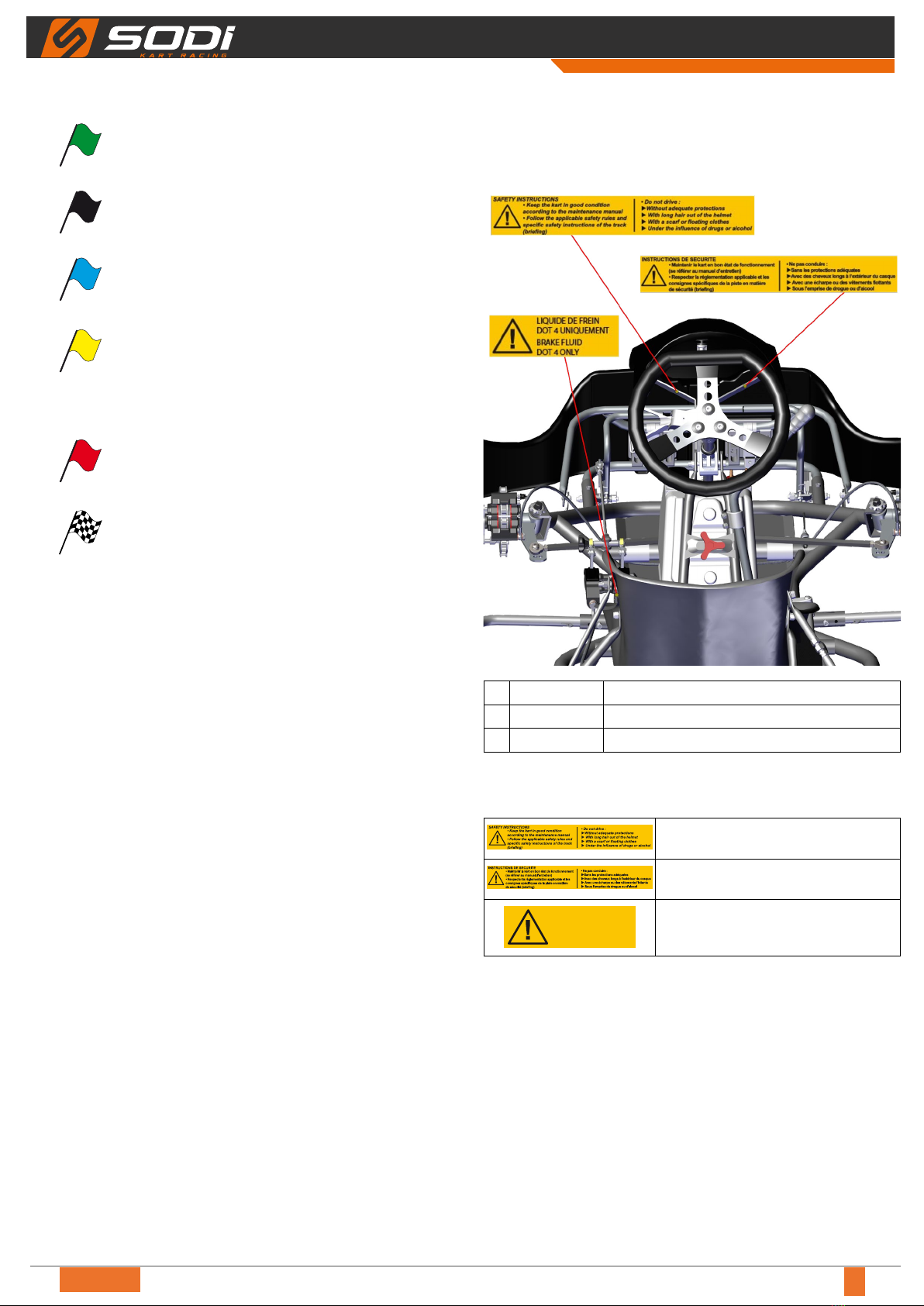
1.3.2 - Safety stickers
Location
1AC701.121 Safety instructions GB sticker
2 AC701.122 Safety instructions FR sticker
3AC701.124 Sticker DOT 4
Meaning
Summary of the main safety
instructions for the driver.
Summary of the main safety
instructions for the driver.
LIQUIDE DE FREIN
DOT 4 UNIQUEMENT
BRAKE FLUID
DOT 4 ONLY
Use brake uid DOT 4 only.
10/2022
6EN
USER AND MAINTENANCE MANUAL
2 - Reception
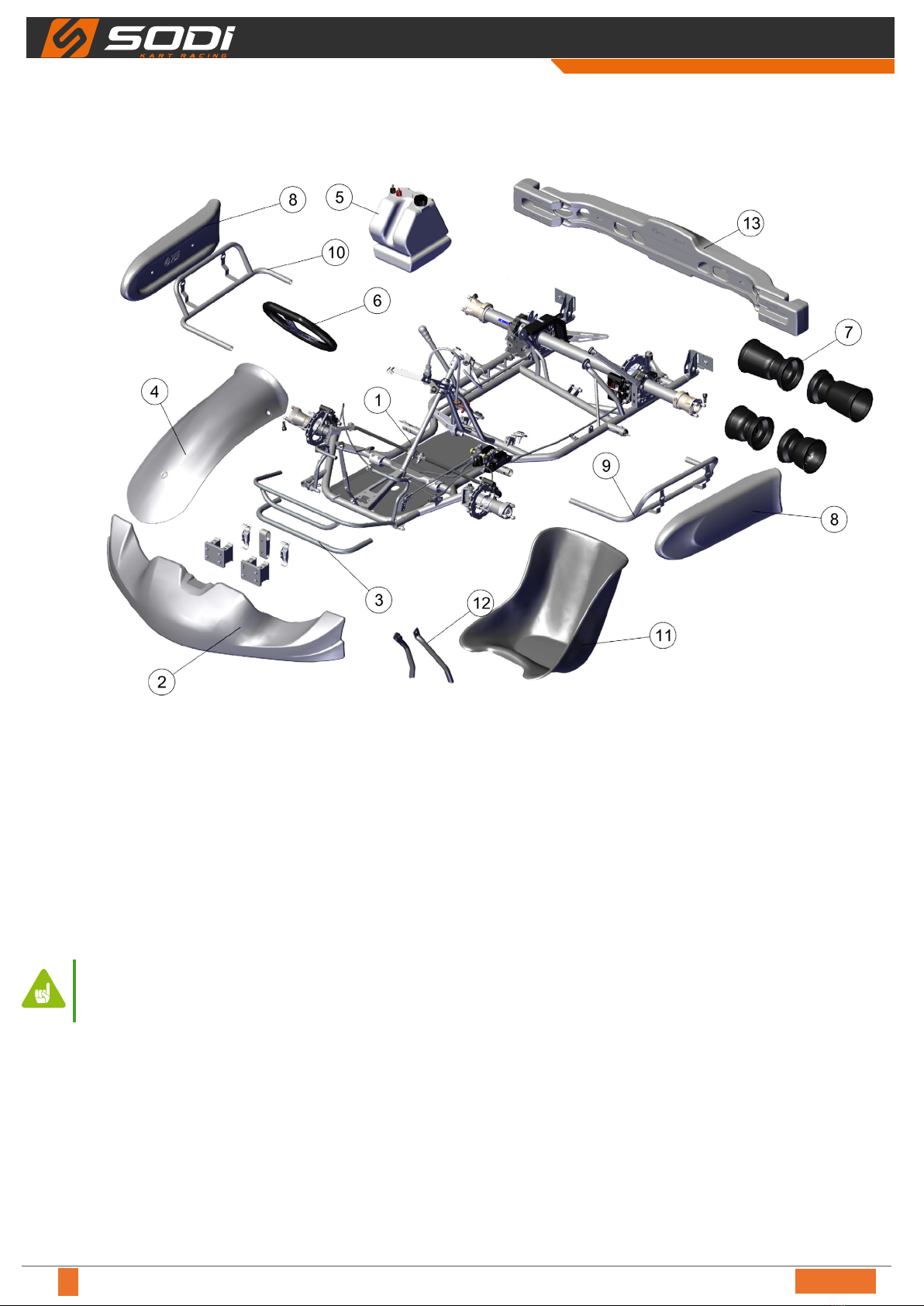
2.1 - Main components
Legend
1 Frame pre-equipped
2 Spoiler
3 Spoiler brackets
4 Nassau panel
5 Fuel tank
6 Steering wheel
7 Rims
8 Side pod
9 Left side pod bracket
10 Right side pod bracket
11 Seat
12 Seat stieners
13 Rear bumper
●At reception of your frame check the presence of
all elements above.
●For part numbers, refer to the spare parts
catalogue.
MAN_Sigma_EN_02
USER AND MAINTENANCE MANUAL
7
EN
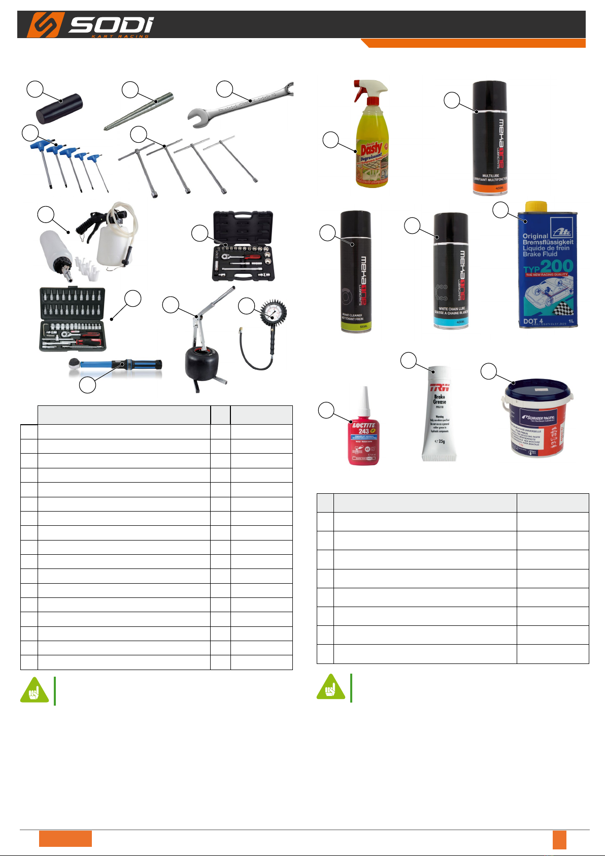
2.2 - Tooling for assembly and adjustment
2
1
5
4
8
7
3
910 11
12
Designations Ø Parts N°
1 Ring centring device (Hub) (*) - OU931.010
2 Stub axle screw centring device (*) - OU931.012
3 Wrench 6
4T-shaped Allen key 3OU911.001
4T-shaped Allen key 4 OU911.002
4T-shaped Allen key 5OU911.003
4T-shaped Allen key 6OU911.004
4T-shaped Allen key 8OU911.005
5 T-shaped socket wrench 8OU912.004
5 T-shaped socket wrench 10 OU912.001
5 T-shaped socket wrench 13 OU912.003
7 Brake bleeding system - OU951.002
8 Socket set 1/2' 22 pcs - OU914.017
9 Socket set 1/4' 46 pcs - OU914.016
10 Tyre iron - OU942.002
11 Manometer - OU943.002
12 Torque wrench - OU914.012
●(*) Supplied with the chassis.
2.3 - Maintenance products
2
1
3
5
7
4
6
8
Designations Parts N°
1 DASTY cleaner degreaser LU837.051
2 MEKAONE multilube LU839.002
3 MEKAONE brake cleaner LU839.003
4 MEKAONE chain grease LU821.001
5TYP200 DOT 4 brake uid LU842.010
6 243 Frenetanch Loctite LU861.001
7 PFG110 grease tube LU823.004
8 Tyre grease LU823.003
●For other tools, accessories and equipment, visit
ITAKA web site.
10/2022
8EN
USER AND MAINTENANCE MANUAL
3 - Assembly
3.1 - Precautions and recommendations
●Tightening torque Ø 6 = 10 to 12 Nm.
●Tightening torque Ø 8 = 12 to 23 Nm.
●Tightening torque Ø 10 = 23 to 47 Nm.
●Tightening torque for Tekneex rear axle bearing 80/50
C4: 8 Nm.
●Tightening torques for rims on hub: 25 Nm.
●M8 bleed screw: 12 Nm.
●M10 bleed screw: 16 Nm.
● Screws without bolts: 1 drop of special glue (LU861.001).
● Lubricate rotating parts, ball joints, gas cable...
●Do not overtighten screws and bolts.
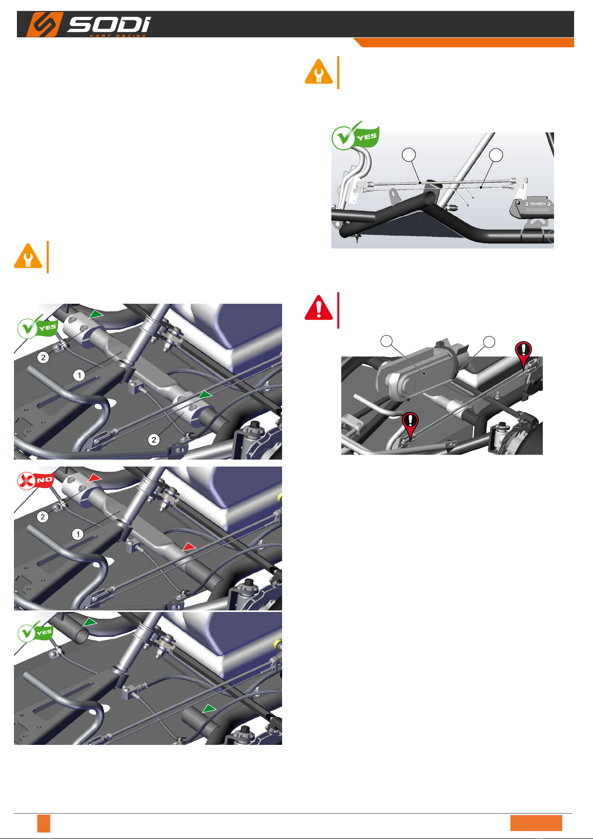
3.2 - Frame stabilizers
Legend
1 Frame stabilizer
2 Stabilizer sleeve
●Always attach the stabilisers to the frame
with a sleeve at each side.
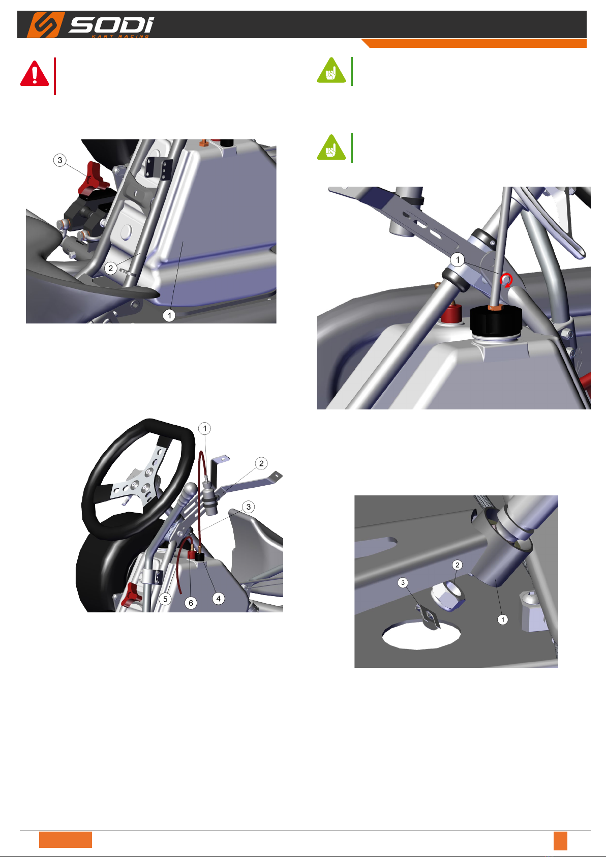
3.3 - Positioning of the safety brake cable
1
2
Legend
1 Safety cable
2 Brake rod
►Always t the safety cable clips (1) under the
staples of the brake rod (2).
12
Legend
1 Spring clip
2 Plastic collar Rilsan
MAN_Sigma_EN_02
USER AND MAINTENANCE MANUAL
9
EN
►Securing clips (1) of the brake control with a
plastic tie Rilsan (2).
3.4 - Assembly of the fuel tank and of the overow
bottle
Legend
1 Fuel tank
2 Steering column support
3 Fly nut
● Insert the fuel tank (1) between the steering column
support (2).
● Tighten the fuel tank (1) with the y nut (3).
Legend
1 Overow bottle
2 Nassau panel support
3 Overow bottle hose
4 Return
5 Petrol tank hose
6 Red plug
● Put the overow bottle (1) on the nassau panel support
(2).
● Connect the overow bottle hose (3) to the return (4).
● Connect the petrol tank hose (5) to the red plug (6).
●Check the presence of the diver under the red
plug.
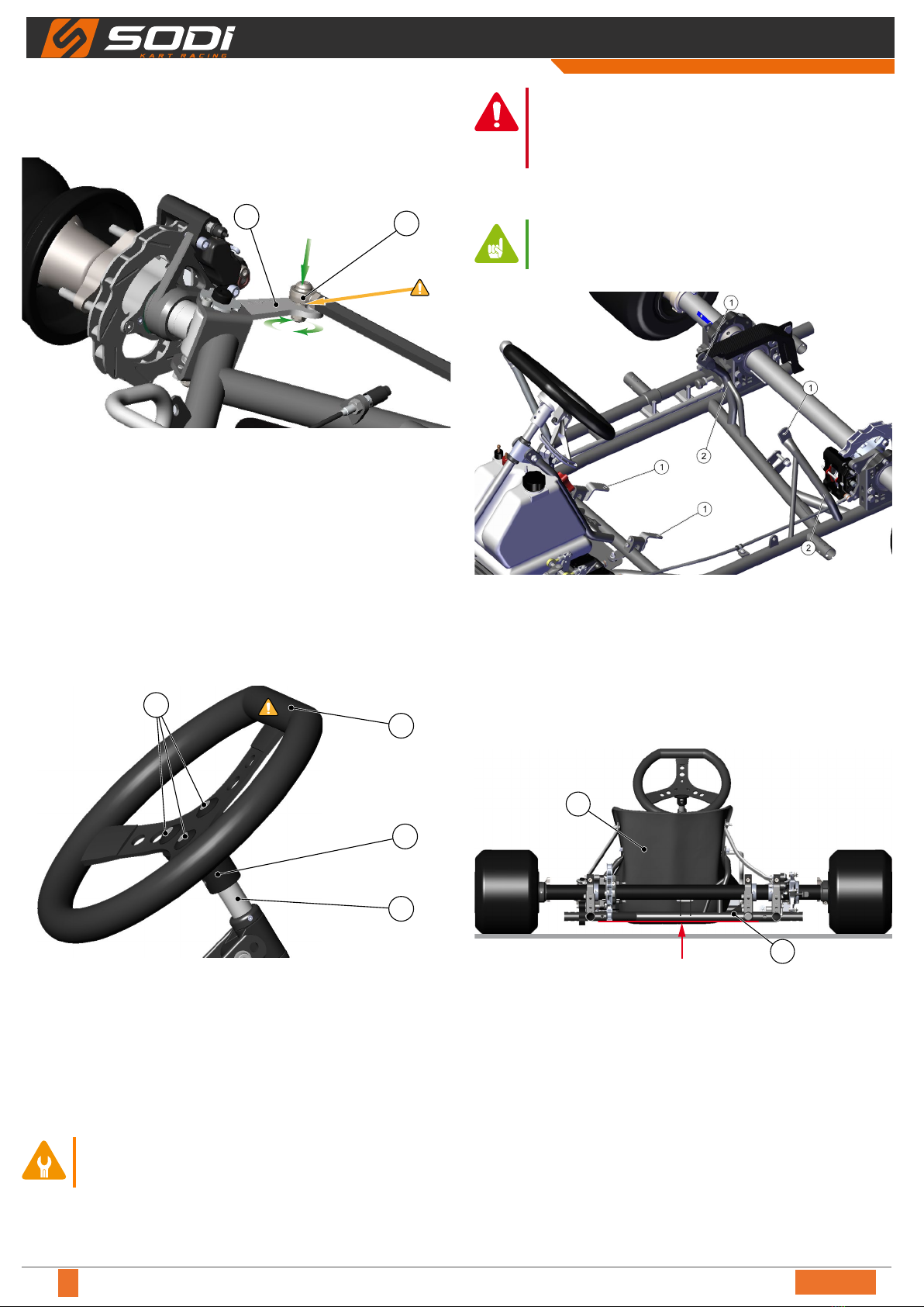
3.5 - Assembly of the steering column and
steering wheel
●See Standard adjustments, p. <EX> for the
assembly dimensions corresponding to the
standard setting recommended for your frame.
Étape 1
Legend
1 Screw + nut
● Tighten the nut (1).
● Tighten the assembly.
Étape 2
Legend
1 Ball joint
2 Nut
3 Fastener clip
● Insert the threaded end of the steering column in the ball
joint (1).
● Tighten the nut (2).
10/2022
10 EN
USER AND MAINTENANCE MANUAL
● Tighten the assembly.
● Put the fastener clip (3).
Étape 3
21
Legend
1 Ball joint
2 Stub axle arm
● Cut the tie-wrap maintaining the stub axles.
● Place the ball joints (1) above the stub axle arm (2).
● Insert the screw into the stub axle arm.
● Place the washer between the ball joint (1) and the stub
axle arm (2).
● Tighten the nut.
● Tighten the assembly.
Étape 4
1
4
3
2
Legend
1 Support
2 Screw
3 Top of the wheel
4 Steering column
● Tighten the steering wheel (straight side up (3)) with the 3
screws (2) on the steering wheel support (1).
● Tighten the steering wheel support (1) on the steering
column (4).
●Once the steering system is assembled,
please check that the steering wheel is free to
make a quarter of a turn right and left.
►A bad assembly or a bad adjustment of
the steering system can lead to accidents.
Systematically check the tightening of the
system and its adjustment.
3.6 - Assembly of the seat
●See Standard adjustments, p. <EX> for the
assembly dimensions corresponding to the
standard setting recommended for your frame.
Legend
1 Fixing points
2 Seat supports
● Get the seat support ends (2) closer, or wider, depending
on the seat size.
● Use the shims of the seat xing kit to get a good t.
Ground clearance
A
1
2
Legend
1 Seat
2 Frame tubes
● Adjust the bottom of the seat (1) with the lower face of
the frame tubes (2).
Indice
Altri manuali Sodi Veicolo utilitario

Sodi
Sodi ekokart lpg Manuale utente

Sodi
Sodi Delta 900 Istruzioni operative

Sodi
Sodi ST32 BV Istruzioni operative

Sodi
Sodi GT4 Istruzioni operative

Sodi
Sodi Sigma DD2 Istruzioni operative

Sodi
Sodi NORDIC Istruzioni operative

Sodi
Sodi Sigma KZ Manuale utente

Sodi
Sodi mini 950 Istruzioni operative

Sodi
Sodi SR4 Istruzioni operative


