-
+
-
+
R5
1K
R1
2.2K
C2
30
C3
30
ZD1
3.9V
C5
224
XTAL
4MHz
<Front> IR_TX
LED2
Q1
8050 VDD
+6V
VDD
78P156
(1602BP)
١١
١٦
١٥٥
١٤
١IC
MOD_RX_IR
DC 4.5V_6V.
BATTERY
+6V+4.5V
POWER SW
SW-SPDT
DATA
R7
1K
R3
1.2K
<Right> IR_TX
LED4
Q3
8050
+6V
١٠
R8
1K
R4
1.2K
<Left> IR_TX
LED3
Q4
8050
+6V
١۲
Front IR_TX
Right IR_TX
Left IR_TX
BUZZER (BiBi)
Right IR_TX
DATA
Motor CON.2-1
Motor CON.1-2
Front IR_TX
Motor CON.2-2
Motor CON.1-1
Left IR_TX
Q5
8550
Q7
8550Q13
C945
Q14
C945
Q9
8050
Q11
8050
R11
10R
R13
10R
A
M2 MOTOR
+4.5V Motor CON.1-2Motor CON.1-1
Q6
8550
Q8
8550Q15
C945
Q16
C945
Q10
8050
Q12
8050
R12
10R
R14
10R
A
M1 MOTOR
+4.5V Motor CON.2-2Motor CON.2-1
٩ ١١ ۸ ١٠ ١٢ ١۸ ١٧ ٢ ١
٩
١۸ ١٧
٢ ١
R15
10K
C1
103
VDD
٤
C4 104
R17
22K
R16
22K
R2
22K
R6
22K
R10
1K
Q2
9013
VDD
۸
BUZZER (BiBi)
BZ1
BUZZER
R18
100R
EC1
100uF
VDD
R9
1K
LED1
RED
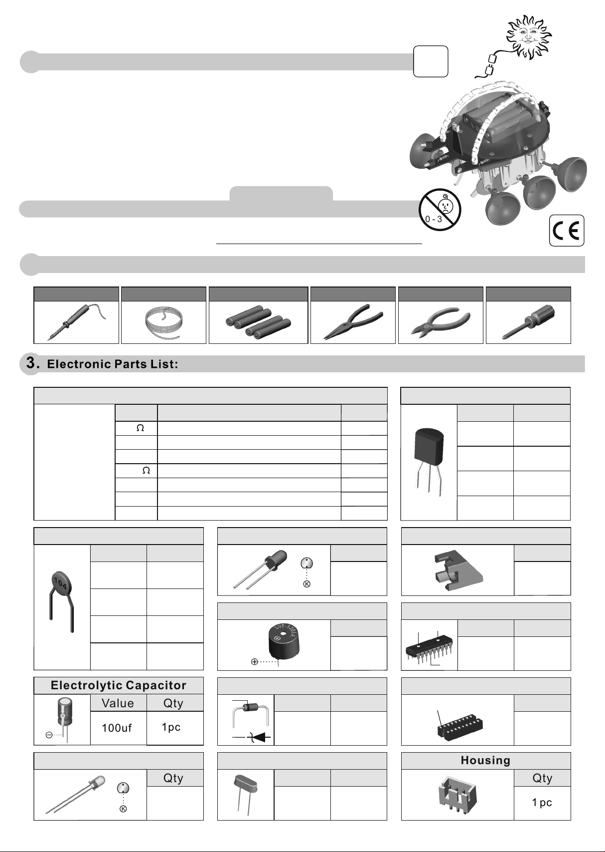
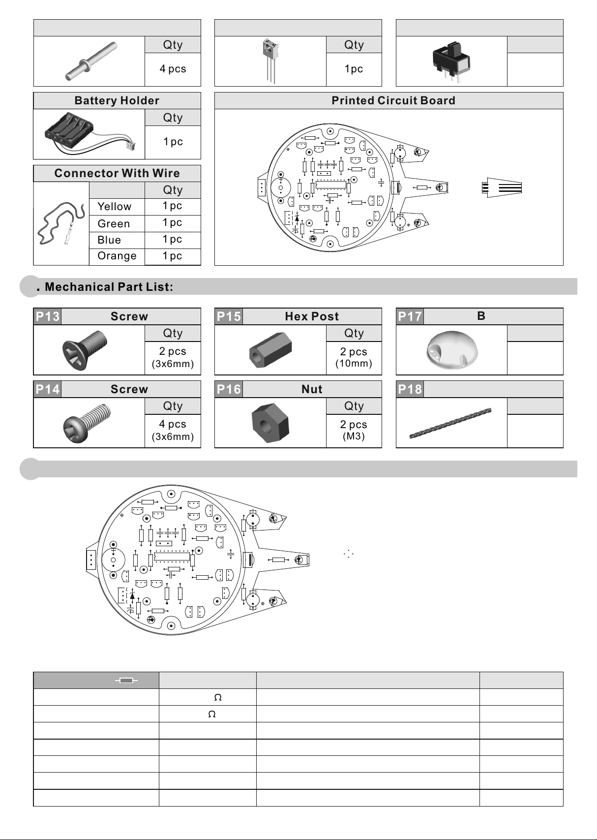
7. How it works:
Switch power to "ON". The LED 1 will light up and the unit will emit 3 beeps as it starts running.
When the unit starts running, the emitting diodes LED2, LED3 and LED4 will send out signals
sequentially to detect obstacles along its path.
Once an obstacle has been detected, the signal received will be transmitted to the receiving module
which will then instruct the Escape Robot to take evasive actions.
aWhen the emitting diode on the right detects an obstacle, the unit will emit a "beep" sound, and
the left motor will go into reverse mode.
bWhen the emitting diode on the left detects an obstacle, the unit will emit a "beep" sound and the
right motor will go into reverse mode.
cWhen the emitting diode in the middle detects an obstacle, the unit will emit two "beeps" followed
by the two motors going into reverse mode. Then, the operation of (a) above is repeated.
dIf all three emitting diodes detects obstacles, the unit will emit three "beeps" and the movement
that follows will be the same as in ( c ) above. However, the turning will take a little longer.
)
)
)
)
1.
2.
8. Trouble shooting:
Ensure that all components on the PCB are in order. Take note especially of the
polarity of the infrared emitting diode.
Different environment and battery power may affect the detecting sensitivity,
try to adjust the Infrared Receiving Module's angle to find the best position.
1.
2.
9. Circuit Diagram:
IR_RX_MOD
21-886
- 18 -