Solarpower mart GAMMA 3.0 Solar Charge Controller Manuale utente

www.solarpower-mart.com Harvest the Sun power!
Thank you for choosing our product!
This manual offers important information and suggestions about the installation, use
and troubleshooting, etc. Please read this manual carefully before using the product
and pay attention to the safety recommendations within.
GAMMA 3.0 Solar Charge Controller With USB Power

www.solarpower-mart.com Harvest the Sun power!
USER MANUAL
GAMMA 3.0 3A - 10A
USB POWER SOLAR CHARGE CONTROLLER
RATINGS (Automatic 12V and 24V)
NOTES: For use with solar panels and battery only
TECHNICAL INFORMATION
Auto 12 / 24 Volt DC
Nominal System Voltage 12 / 24VDC
Maximum PV Input Voltage 50V
Nominal Charge / Discharge Current 3A, 5A and 10A
The controller will recognize the system rated voltage when started up. If the battery
voltage is lower than 18V, it will recognize the system as 12V. If the battery voltage is
greater than 18V, it will recognize the system as 24V.

www.solarpower-mart.com Harvest the Sun power!
Notes, Cautions and Warnings
This manual contains important safety, installation and operating instructions. The
following symbols are used throughout this manual to indicate potentially dangerous
conditions or mark important safety instructions, please take note of them.
WARNING: Indicates a potentially dangerous condition. Use extreme caution when
performing this task.
CAUTION: Indicates a critical procedure for safe and proper operation of the controller.
Note: Indicates a procedure or function that is important for the safe and proper
operation of the controller.
General Safety Guideline
Read all of the instructions and cautionary symbols in the manual before
beginning installation.
There are no serviceable parts inside the controller. Do not disassemble or
attempt to repair it.
Install external fuses/Mini Circuit Breaker (MCB) as required.
Disconnect the solar panel (module/PV) and fuse/MCB near the battery before
installing or adjusting the controller.
Do not allow water to enter the controller.
Confirm that power connections are tightened to avoid excessive heating from a
loose connection.

www.solarpower-mart.com Harvest the Sun power!
General Information
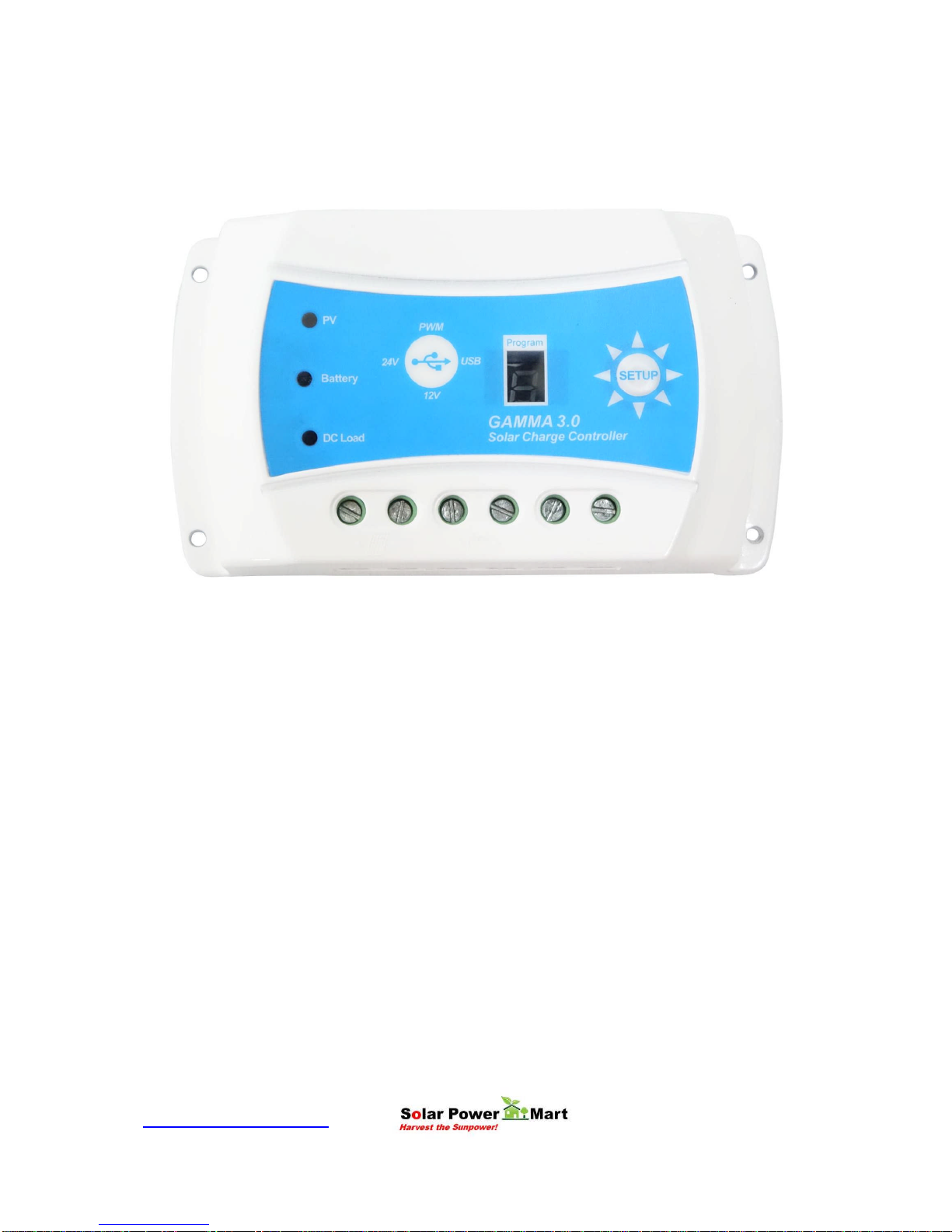
Thank you for selecting GAMMA 3.0 series solar controller that adopts the most
advanced digital techniques programming and is fully automatic. The Pulse Width
Modulation (PWM) battery charging can greatly increase the lifetime of the battery. It
has various unique functions, such as:
12/24V automatic recognition.
Highly efficient Series PWM charging increases the battery life and improves the
solar PV system’s performance.
Uses MOSFET as electronic switch.
Widely used, automatically recognize day/night technology for 12/24V and 5V.
New SOC method of calculating accurately displays the available battery
capacity.
Intelligent timer function with 1-14 hours for both 12/24V and 5V USB
Unique USB Power timer function, enhance the flexibility of lighting system
Automatic select battery type (No equalization charge) and design for: Gel,
Sealed, Flooded and Lithium (in house battery).
Adopts temperature compensation, corrects the charging and discharging
parameters automatically and improves battery life.
Electronic protection from overheating, over charging, over discharging,
overload, and short circuit.
Reverse protection: any combination of solar module and battery.
Support On Grid (grid-tie) solar panel (maximum PV voltage input 50V).
The controller is for multipurpose off-grid solar systems and enhances off grid solar
system, protects the battery from being over charged by the solar module and over
discharged by the loads. The charging process has been optimized for long battery life
and improved system performance. The comprehensive self-diagnostics and electronic
protection functions can prevent damage from installation mistakes or system faults.
Although the controller is easy to operate and use, please kindly study this user manual
before you begin. This will help you make full use of the functions and you can improve
your solar system.

www.solarpower-mart.com Harvest the Sun power!
Product Features
1. PV (Solar Panel) Charging Status LED indicator
A LED indicator that shows charging status and also indicates warning signal when solar array
connect wrongly.
2. Battery Status LED Indicator
A LED indicator that shows battery status and other crucial information.
3. Load On & Off Switch, Setup & Program
Manually turn on or turn off the DC load.
4. DC Load LED Indicator
Display the load status.
5. Solar Module Terminals
Connect solar modules.
6. Battery Terminals
Connect batteries.
7. Load Terminals
Connect loads.
8. Display
Program display for timer and modes.
(1)
(8)(2) (3)
(4)
(5) (6) (7)

www.solarpower-mart.com Harvest the Sun power!
9. USB Power Socket
Connect to USB devices (5VDC, 1.2A).
(9)

www.solarpower-mart.com Harvest the Sun power!
Installation
General Installation Notes:
Read through the entire installation section first before beginning installation.
Be careful when working with batteries. Wear eye protection if necessary. Have
fresh water available to wash and clean any contact with battery acid.
Uses insulated tools and avoid placing metal objects near the batteries.
Explosive battery gasses may be present during charging. Be certain there is
sufficient ventilation to disperse the gasses.
Avoid direct sunlight and do not install in locations where water can enter the
controller.
Loose power connections and/or corroded wires may result in resistive
connections that melt wire insulation, burn surrounding materials, or even cause
fires. Ensure tight connections and use cable clamps to secure cables and
prevent them from swaying from mobile applications.
Use with Lithium (our in house product), Gel, Sealed or Flood batteries only.
Battery may be wired to one battery or more batteries. The following instructions
refer to the use of a single battery, but the battery connection can be made to
either one battery or a group of batteries in a battery bank.
Select the system cables accordingly or consult us for more details.
Mounting Requirements
NOTE: When mounting the controller, ensure there is free air flow through the controller
heat sink fins. There should be at least 6 inches (150 mm) of clearance above and
below the controller to allow for cooling. If mounted in an enclosed space, providing
ventilation is highly recommended.
WARNING: Risk of explosion! Never install the controller in a sealed enclosed area
with flood batteries! Do not install in a confined area where battery gases can
accumulate.

www.solarpower-mart.com Harvest the Sun power!
Step 1: Choose Mounting Location
Place the controller on a vertical surface protected from direct sunlight, high
temperature, and moisture. Provide good ventilation.
Step 2: Check for clearance
Place the controller at the location where it will be mounted. Verify that there is
sufficient room to run the wires and that there is sufficient room above and below the
controller for air flow.
Step 3: Mark Holes
Use a pencil or pen to mark the four (4) mount points on the surface.
Step 4: Drill Holes
Remove the controller and drill 3.6mm holes in the marked locations.
Step 5: Secure Controller
Place the controller on the surface and align the mounting holes with the drilled holes in
step 4. Secure the controller in place using the mounting screws.

www.solarpower-mart.com Harvest the Sun power!
Wiring
NOTE: A recommended connection order (step by step) has been created to provide
maximum safety during installation.
NOTE: The controller is a common positive ground controller.
CAUTION: Do not connect the loads with surge power exceeding the rating of the
controller.
CAUTION: For mobile applications, be sure to secure all wiring. Use cable clamps to
prevent cables from swaying when the vehicle/object is in motion. Unsecured cables
create loose and resistive connections which may lead to excessive heating and/or fire.

www.solarpower-mart.com Harvest the Sun power!
Step1: Battery Wiring
WARNING: Risk of explosion or fire! Never connect the positive (+) and negative
(-) battery cables.
Before battery is connected, make sure that the battery voltage is greater than 6V to
start up the controller. If the system is 24V, make sure battery voltage is not less than
18V. During the first start up, the controller will automatically recognize the system
voltage.
When installing a fuse or Mini Circuit Breaker (MCB), make sure that the distance
between the fuse holder and the positive terminal of battery does not exceed 150mm.
Do not insert a fuse (MCB) at this time.
Make sure the battery cable is less than 0.5 meter long to prevent power loss.
Always keeps the controller as close as possible so that it can sense the battery
temperature for effective charging (temperature compensation).
Indice


