SORG Dynamis MV Manuale di servizio

Service record Dynamis MV 1 von 36
2021-01-12 Besondere Menschen, besondere Lösungen.
ENG
Unique people, unique solutions.
Service record Dynamis MV
Service recordService record
All individual adjustments to the
Wheelchair described. Tools and specialist knowledge are required for
these settings. Please leave these adjustments to a qualied rehabili-
tation specialist.
Dynamis MVDynamis MV

2 von 36 Service record Dynamis MV
Service record Dynamis MV 2021-01-12
Impressum
SORG Rollstuhltechnik GmbH + Co. KG
Benzstraße 3-5
68794 Oberhausen-Rheinhausen / Germany
Fon +49 7254-9279-0
Fax +49 7254-9279-10
Mail [email protected]
Web www.sorgrollstuhltechnik.de
Revision status
2021-03-15
Technical status
We reserve the right to make technical chan-
ges and misprints. The images can dier from
the actual individual equipment components.
The handling is to be carried out accordingly.
Gender note
For editorial reasons for better readability, only
the masculine form is used. Corresponding
terms apply in the sense of equal treatment to
all genders and do not represent any valuation.
Copyright
All content, especially texts, photographs and
graphics, are protected by copyright. All rights,
including copying, publishing, editing and
translating, are reserved. © by SORG Rollstuhl-
technik GmbH + Co. KG Benzstrasse 3-5, 68794
Oberhausen-Rheinhausen / Germany.
You can nd our general terms and condi-
tions on our order sheets and at www.sorgroll-
stuhltechnik.de/impressum.

Service record Dynamis MV 3 von 36
2021-01-12
1 The wheelchair at a glance 4
2 General information 5
2.1 General information service booklet 5
2.2 Documentation notes 5
2.3 Required torques and tools 5
2.4 Explanation of symbols 6
2.5 General safety information 7
3 Assemblys 8
3.1 Wheel assembly 8
3.1.1 Center of gravity (wheelbase / perfo-
rated plate) 8
3.1.2
Adjustment of the seat height by
changing the position of the caster wheel
8
3.1.3 Rear seat height, seat inclination 9
3.1.4 Caster head tilt 9
3.1.5 Replacement / relocation of the caster
wheel adapters and caster wheels 10
3.1.6 Camber 10
3.1.7 Track compensation drive wheels 11
3.2 ERGO-seat assembly 12
3.2.1 General information about the ERGO
seat 12
3.2.2 Removal of the ERGO seat 12
3.2.3 Axis of rotation seat part / back part 13
3.2.4 Growth in seat depth ERGO seat 13
3.2.5 Adjusting the seat height 13
3.2.6 Increase seat width ERGO seat and back
unit 14
3.3 Frame assembly 15
3.3.1 Frame widening 15
3.4 Back assembly 16
3.4.1 Setting dynamic back 16
3.4.2 Back angle adjustment 16
3.5 Legrest assembly 17
3.5.1 Adjustment of the legrest 17
3.5.2 Adjustment of the depth 17
3.5.3 Adjusting the height 18
3.5.4 Preset opening angle 18
3.5.5 Height adjustment of the calf support18
3.5.6 Height adjustment of the footrest 19
3.6 Brakes assembly 20
3.6.1 General information about the brake
20
3.6.2 Standard parking brake 20
3.6.3 Drum brake 21
3.7 Anti-tipper assembly 22
3.7.1 Height adjustment 23
3.7.2 Length adjustment 23
3.8 Tilt bracket assembly 24
3.8.1 Mounting 24
3.9 Headrest assembly 25
3.9.1 Height adjustment 25
3.9.2 Depth adjustment and dynamics of the
headrest 25
3.9.3 Adjust the inclination 25
3.10 Abduction wedge assembly 26
3.10.1 Depth adjustment 26
3.10.2 Height adjustment 26
3.11 Lateral support assembly 27
3.11.1 Nomenclature 27
3.11.2 Vertical adjustment 27
3.11.3 Horizontal setting 27
3.11.4 Fine adjustment of the lateral support
holder 28
3.11.5 Adaptation to the user 28
4Repairs / maintenance / re-use 29
4.1 Rapairs 29
4.2 Spare parts 29
4.3 Cleaning 29
4.4 Disinfection 29
4.5 Storage 29
4.6 Lifespan 30
4.7 Re-use 30
4.8 Disposal 30
4.9 Maintenance / inspection 30
5 Technical data 31
5.1 Data and dimensions 31
5.2 Meaning of the labels 32
5.3 Declaration of Conformity 32
Contents

4 von 36 Service record Dynamis MV
Service record Dynamis MV 2021-01-12
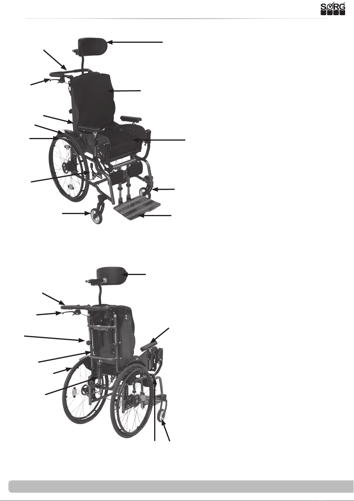
1 The wheelchair at a glance
14 headrest
15 push bow
16 control lever for drum brake
17 star grip for height adjustment of the
push handle
18 armrest
19 back guide
20 drive wheel
21 shock absorbers
22 Brake lever of the knee lever brake
23 caster wheel
22
21
19
18
17
16
23
15
20
14
1 headrest
2push bow
3drum brake control lever
4 anatomical back cushion
5 Ergo-seat
6 drive wheel
7 handrim
8anatomical seat cushion
9knee lever brake
10 footplate
11 caster fork
12 caster wheel
1
5
6
9
8
12
4
3
2
11
7
10

Service record Dynamis MV 5 von 36
2021-01-12
2 General Information
All individual settings, adjustments, repairs and the annual inspection of the wheelchair are
described below. This requires tools and special expertise. Please leave these adjustments to a
qualied specialist retailer.
Adjustments that can be made by the attendant are described in the instructions for use.
If you have any questions or comments, please contact your specialist retailer or our team (+49
7254 9279-0).
• M5: 5 Nm;
• M6: 7 Nm;
• M6 (perforated plate) 10 Nm
• M8: 20 Nm;
• M10 (nut): 25 Nm; (caster wheel)
• Thru axle tting 40 Nm
• Torque wrench (5-50 Nm)
• Open-ended wrench
• Reversible ratchet with socket wrench inserts
• Hexagon screwdriver
• Phillips screwdriver
• Slotted screwdriver
• Plastic hammer
• Side cutter
• Thread locking liquid
• Bicycle tube repair kit
• Workbench / vice with plastic jaws
• Special open-end wrench for adjusting the shock absorber
2.1 General information on the service booklet
2.2 Documentation notes
2.3 Required torques and tools
Torque required for the following screws:
Needed tools:
Please note:
• You can nd advance booking information on our website at www.sorgrollstuhltechnik.de
• Information for the user can be found in the instructions for use
• Maintenance information can be found under: Chapter 4 (Repair / Maintenance / Re-use)

6 von 36 Service record Dynamis MV
Service record Dynamis MV 2021-01-12
2 General information
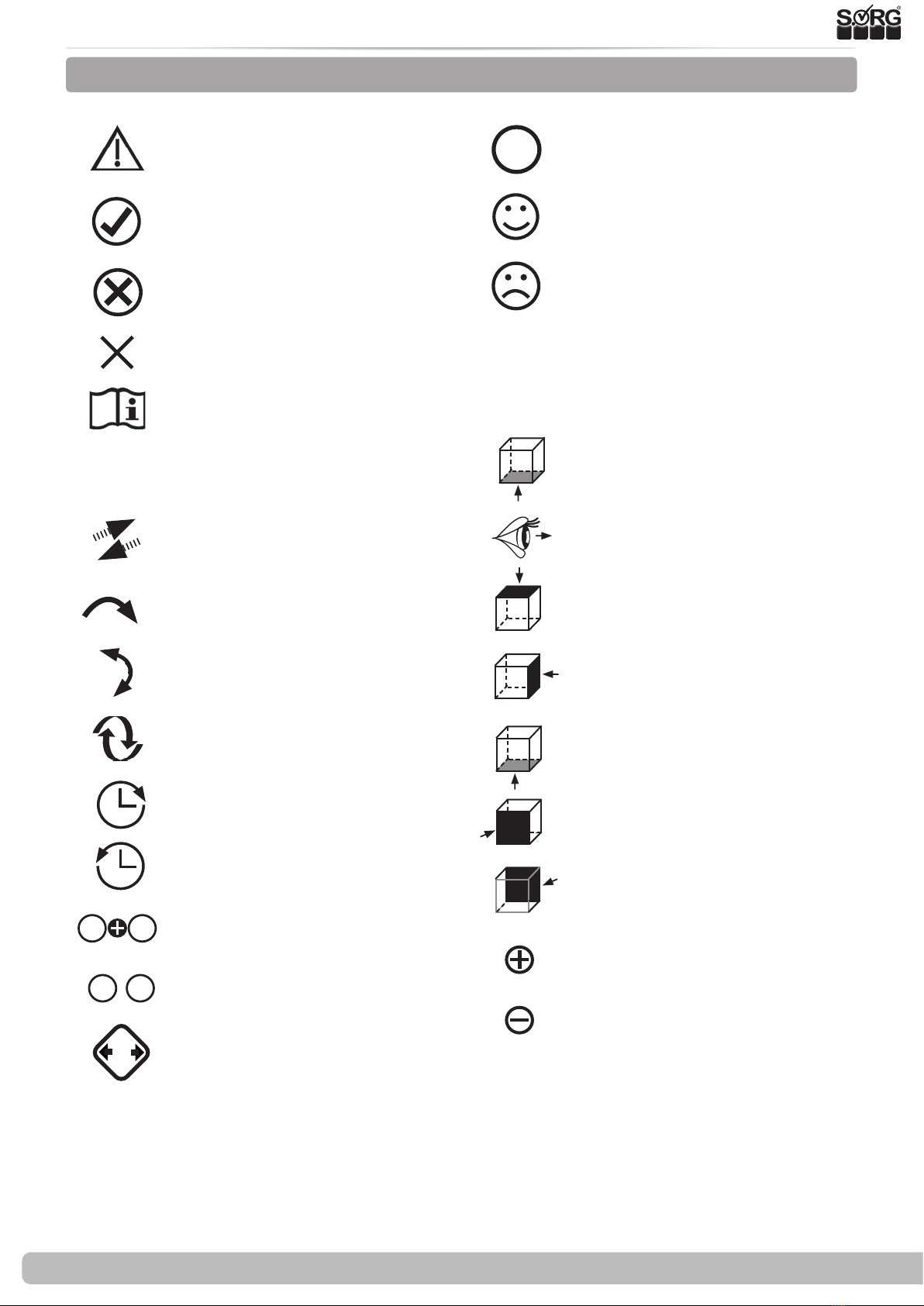
2.4 Explanation of symbols
ATTENTION! Warnings for per-
sonal safety issues, of the utmost
importance
CORRECT safety relevant setting/
handling
WRONG adjustment/ handling
PROHIBITED
Reference to additional / further
reading.
Set or adjust the angle
Open / close
Turn clockwise
Turn counterclockwise
Steps to be performed at the
same time
Steps to be performed in se-
quence
Steps to be performed on both
sides
Handling
(A); (B)
1. 1.
1. 2.
;
2x2x
Push / pull / insert / move / re-
move
Push in a certain direction
Important detail / element
Correct or proper setting / use
Inadmissible or incorrect setting
/ use
Reference from text to detail
perspective
View from above
Side view
View from below
Front view
Rear view
Attach part
Remove part

Service record Dynamis MV 7 von 36
2021-01-12
2 General information
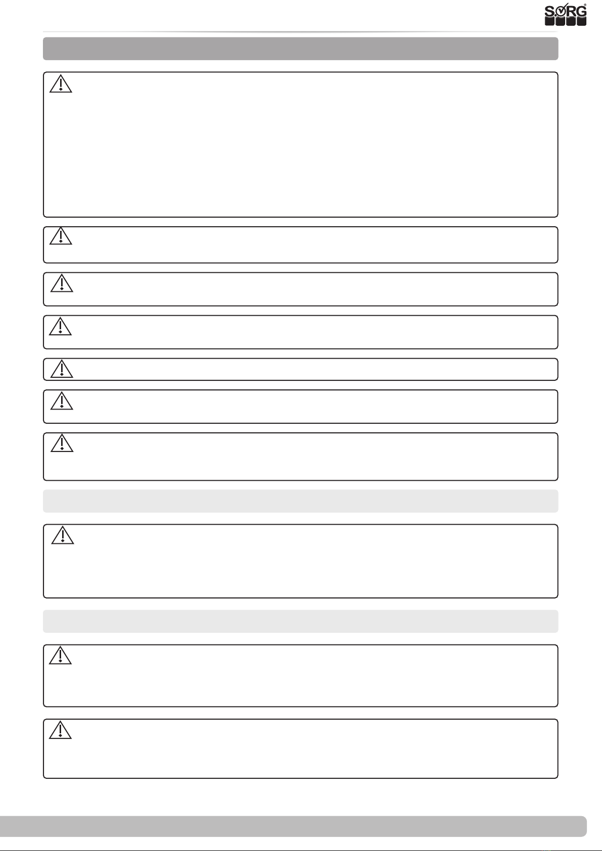
2.5 General safety information
Check before every ride:
• Frame, back unit, add-on parts and accessories for visible damage, bends, cracks or mis-
sing / loose screws,
• Wheels / thru axles on tight t ,
• sucient tire pressure, tire prole,
• Functionality of the brakes,
• tight t of the angle adjustment elements / eccentric clamps,
• rm closure of the seat plate / back / foot plate,
• functionality of the anti-tips / seat and back straps,
• whether all previously dismantled parts are reinserted and rmly locked.
There is a risk of injuries (e.g. crushing) on all rotating, rotatable or foldable parts, also
during adjustment and repair work as well as during transport.
All wheelchair parts are to be handled properly. Do not throw or drop removable parts!
Before starting the test, repair or adjustment work, clean / disinfect the wheelchair and
secure it against tipping over and / or falling.
Use only original spare parts.
Safety nuts may only be used once. Safety nuts that have been loosened must be repla-
ced with new ones.
Only regular maintenance of all safety-relevant parts on the wheelchair by a qualied
rehab workshop protects against damage and maintains our manufacturer's warranty.
Lifespan
Use beyond the specied service life leads to an increase in the residual risks and should
only be carried out after careful, qualied consideration by the operator. If the service life is
reached, the user or a responsible person should contact the specialist retailer. There you can
get information about the possibility of reconditioning the product.
Combination with products from other manufacturers
The wheelchair may only be combined with the additional electrical drives approved by the
manufacturer. Restrictions or adjustments as well as the cultivation itself are the responsibility
of the provider of the additional system or the authorized specialist retailer. Please ask the ma-
nufacturer of the additional drives for the requirements.
In the combination of a wheelchair and an additional electric drive, particular loads occur
that can damage the wheelchair. Approach obstacles slowly and overcome them carefully so
that little force is exerted on the caster wheel, drive wheel and the wheelchair as a whole.

8 von 36 Service record Dynamis MV
Service record Dynamis MV 2021-01-12
3.1 Wheels assembly
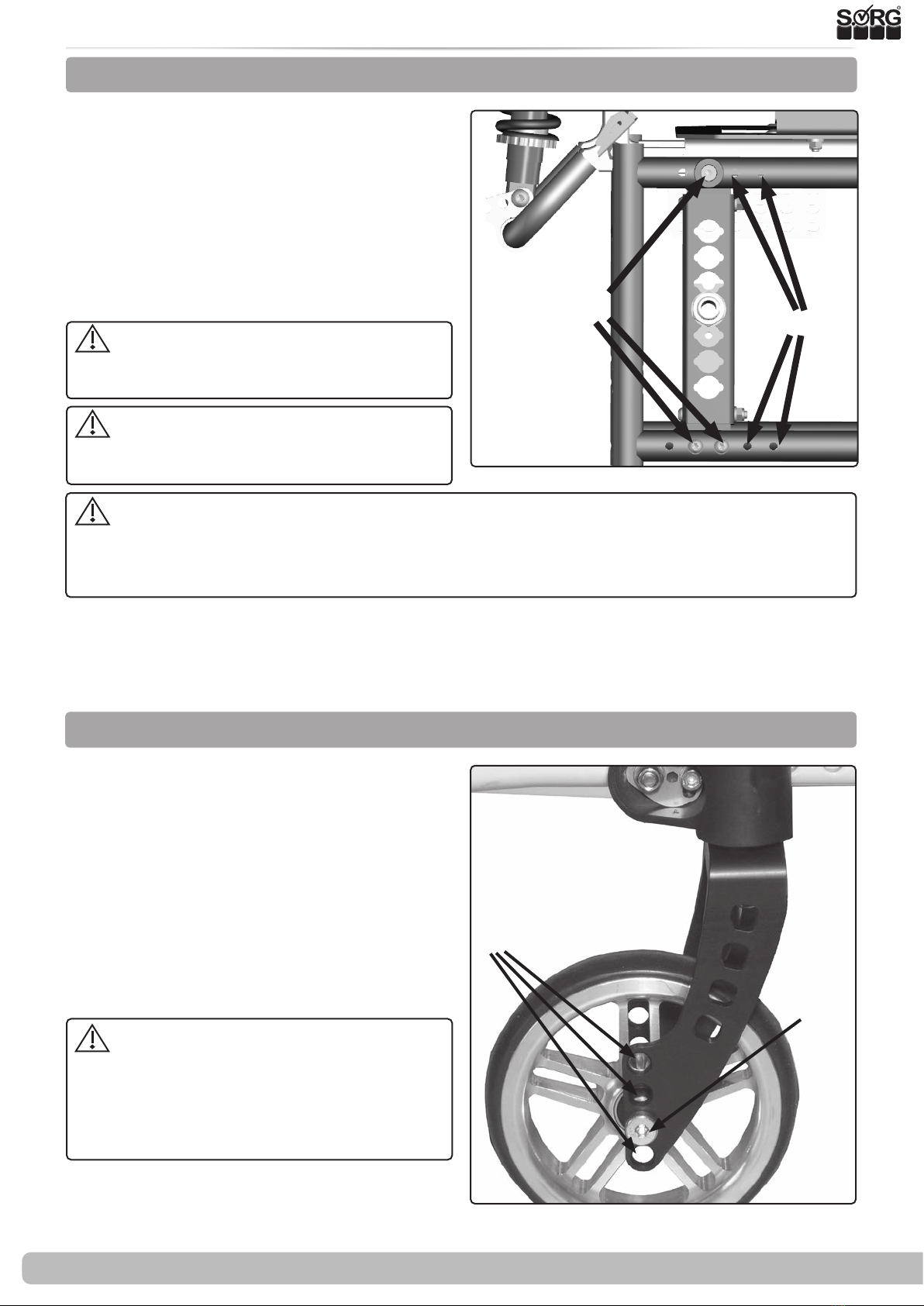
3.1.1 Center of gravity (wheelbase / perforated plate)
3.1.2
Adjustment of the seat height by changing the position of the caster wheel
(1)
(A) (B)
(1) To adjust the center of gravity
• remove both drive wheels,
• remove all screws (A) and nuts
• move the perforated plate into the al-
ternative holes (B).
• Moving must be done in parallel on
both sides.
• Reinstall screws and nuts and tighten
tightly.
The parking brakes must be readjusted
after every change to the drive wheels.
Go carefully to the maximum and the
user (!) Desired point of tilt.
The further back you move the caster wheels, the greater the risk of the wheelchair tip-
ping forward when getting in and out.
The further you mount the drive wheels with the perforated plate to the front, the greater the
risk of the wheelchair tipping backwards.
When tilting the seat, please make sure that the gripping point and gripping path are not im-
paired by setting the drive wheels too high.
The drive wheel mount can be adjusted horizontally by up to 60 mm from the most passive po-
sition (0 mm).
(2)
(A)
(B)
(2) The front seat height is adjusted via the po-
sition of the caster wheel in the caster fork.
• Completely remove the caster wheel /
caster fork screw connection (A),
• Fasten the caster wheels in the desired
hole (B) on both sides,
• tighten all screws again.
After every change you have to check the
vertical tilt of the caster head and correct it if
necessary (see chapter caster head tilt).
Hair, lint, dirt, etc. collect on the bea-
rings of the caster wheels, making the cas-
ter wheels sti. Remove the caster wheels
at short intervals and thoroughly clean the
forks, axles and sleeves.
Please proceed in the same way with plastic
forks.

Service record Dynamis MV 9 von 36
2021-01-12
3.1 Wheels assembly
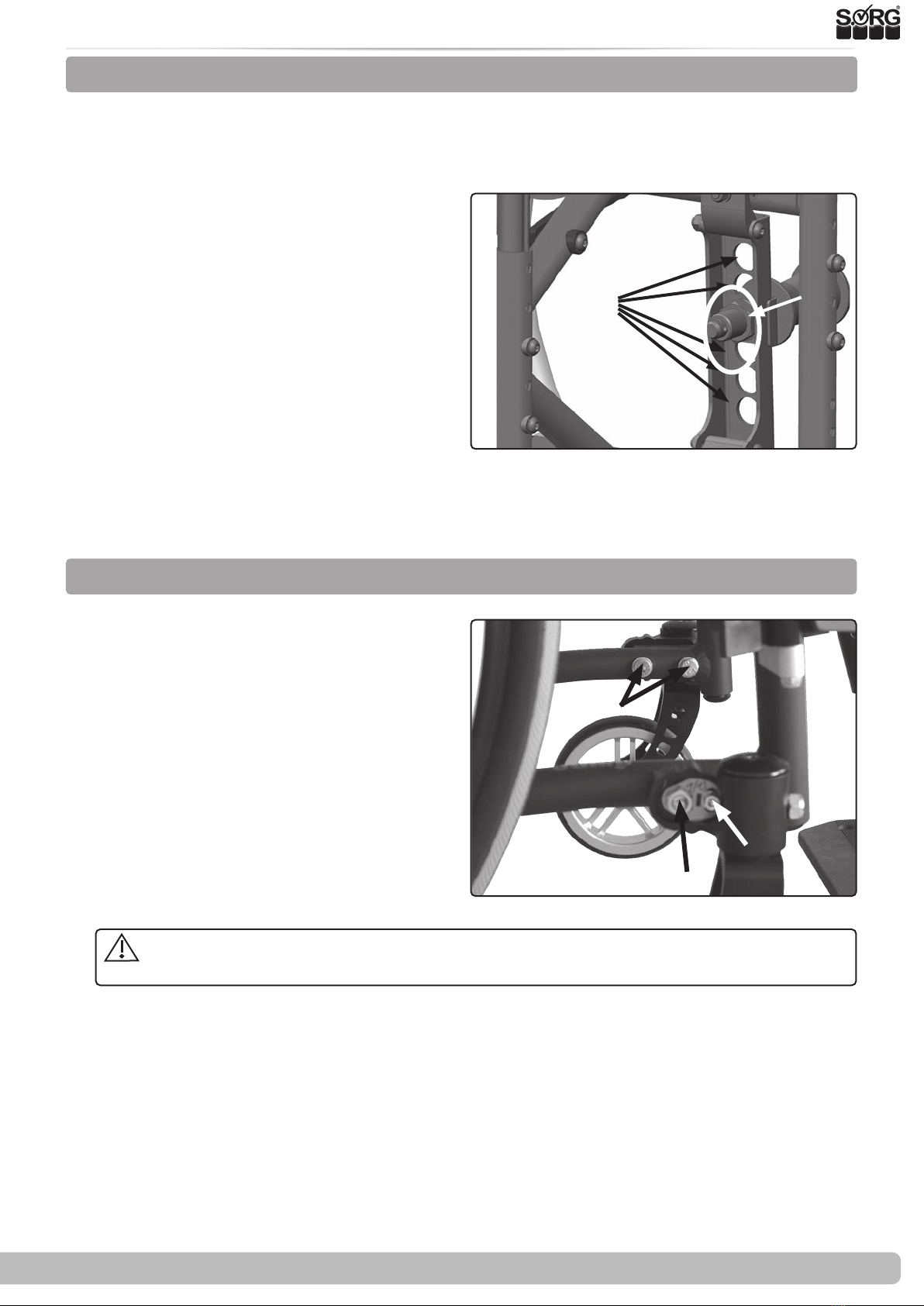
3.1.3 Rear seat height, seat inclination
(1)
(B) (A)
As a rule, the seat height at the back is selected approx. 2-3 cm lower than the seat height at
the front in order to achieve a safe and comfortable sitting position with good distribution of
the seat pressure and to avoid "slipping forward". However, other settings can also be useful in
individual cases.
• (1) Remove the drive wheels and remo-
ve the quick release axle tting (A) with
all washers,
• move the quick-release axle tting in-
cluding all washers into the alternative
holes (B)
• and tighten all screws again. (Tightening
torque of nuts M18 tting 40 Nm).
• Mount the side parts and put the drive
wheels back into the quick-release axle.
The ttings must protrude equally far out of the perforated plate on both sides. The ttings may
only be unscrewed so far that the lateral distance between the tires at the top and the side panel
is as small as possible, but at least 10 mm.
3.1.4 Caster head tilt
The caster head inclination must be readjusted
after every change to the drive wheel.
For adjusting the caster wheel adapter:
• (3) Loosen all screws (A) (B) on both
sides.
• Bring the adapters into an exactly ver-
tical position by turning the adjusting
washer (C) (using a at-blade screwdri-
ver) (create an angle).
• Tighten all screws again; Screws (A)
with 9 Nm, screw (B) with 7 Nm
(2)
(B)
(C)
(A)
An incorrectly set caster head inclination can lead to caster wheel utter and when cor-
nering (due to the wheel caster) to cumbersome "uphill and downhill driving".

10 von 36 Service record Dynamis MV
Service record Dynamis MV 2021-01-12
3.1 Wheels assembly
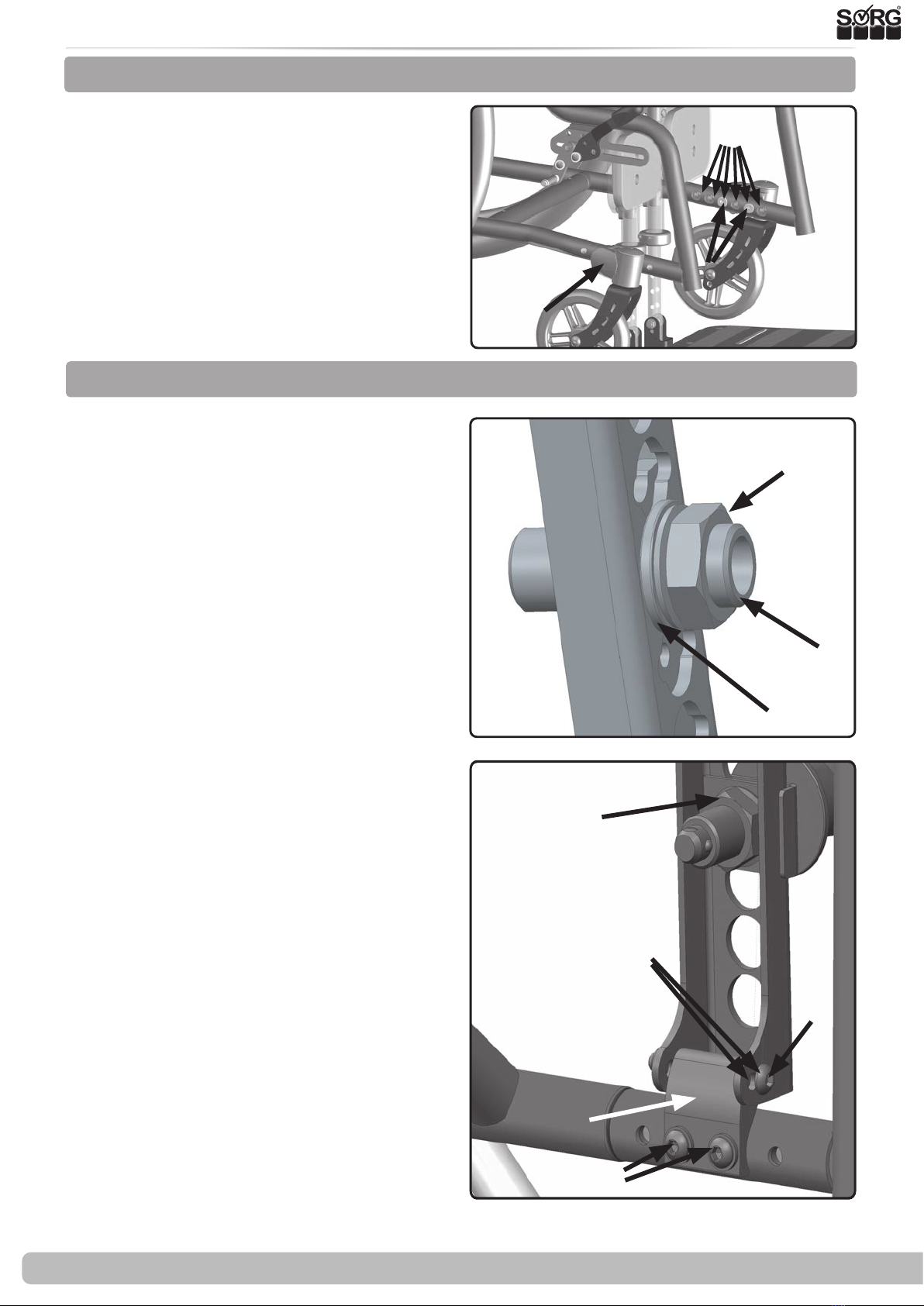
• (1) Remove the caps on both sides (A),
• remove all screws on both sides (B)
• and remove the spacers if necessary.
• Replace the caster wheel adapters with
new ones and / or move them to the
alternative holes (C).
• Reinsert all screws (including the spa-
cers, if applicable) and tighten them
tightly.
3.1.5 Replacement / relocation of the steering wheel adapters and caster wheels
(1)
(A)
(B)
(C)
You inuence through the camber:
• the lateral tipping stability
• the shoulder drive wheel position and
• the track width of the wheelchair.
(2) To avoid the so-called "eraser eect", we install
the appropriate track compensation (A) at the
factory. If the camber is changed at a later date,
the toe compensation adapter (A) must be repla-
ced with a suitable one (spare part).
With a wheel camber of 8 °, a spacer block is re-
quired to extend the wheelbase (spare part).
Adjust the camber:
• (3) Remove drive wheels,
• Remove the screw connection (A) and
move it into the alternative holes (B),
• tighten the screw connection again.
For a camber of 8 °:
• (3+1 next page) remove the screw con-
nection (A),
• remove the screw connection (C),
• move the perforated plate holder (D) by
turning it 180 ° on the outside of the frame
tubes,
• insert the screw connection (C) again and
tighten the screws (C) tightly,
• reinsert the perforated plate with the screw
connection (A) and tighten the screws (A).
The setting may not be possible if you want to
widen the seat, otherwise you will have to unscrew
the quick-release axle ttings too far out of the
perforated plate.
3.1.6 Camber
(3)
(B)
(C)
(A)
(D)
(2)
(A)
(B)
(E)
(C)
Indice
Altri manuali SORG sedia a rotelle

SORG
SORG Mio Carbon Design 2018 Manuale utente

SORG
SORG Tilty vario Manuale utente

SORG
SORG Tilty vario Manuale utente

SORG
SORG MIO MOVE Manuale utente

SORG
SORG Vector Manuale di servizio

SORG
SORG Siro II Manuale utente

SORG
SORG Dynamis MV 793 Manuale utente

SORG
SORG Loop 802 Manuale di servizio

SORG
SORG MIO MOVE Manuale di servizio

SORG
SORG MIO MOVE Manuale di servizio

SORG
SORG Jump alpha Manuale utente

SORG
SORG Jump alpha Manuale di servizio

SORG
SORG Vector Manuale utente

SORG
SORG Mio Move 604 Manuale utente

SORG
SORG Tilty vario Manuale di servizio

SORG
SORG LoopSORG 802 Manuale utente

SORG
SORG Tilty vario Manuale di servizio

SORG
SORG Mio Manuale utente

SORG
SORG kika Manuale utente

SORG
SORG Loop 802 Manuale utente