NTRODUCT ON
This Owner’s Manual is intended to compl with all Australian Occupational or Workplace Health and Safet
Regulations regarding the manufacturer’s provision of information to the owner or purchaser of work plant. The
information is correct at the date of publication.
APPL CAT ON
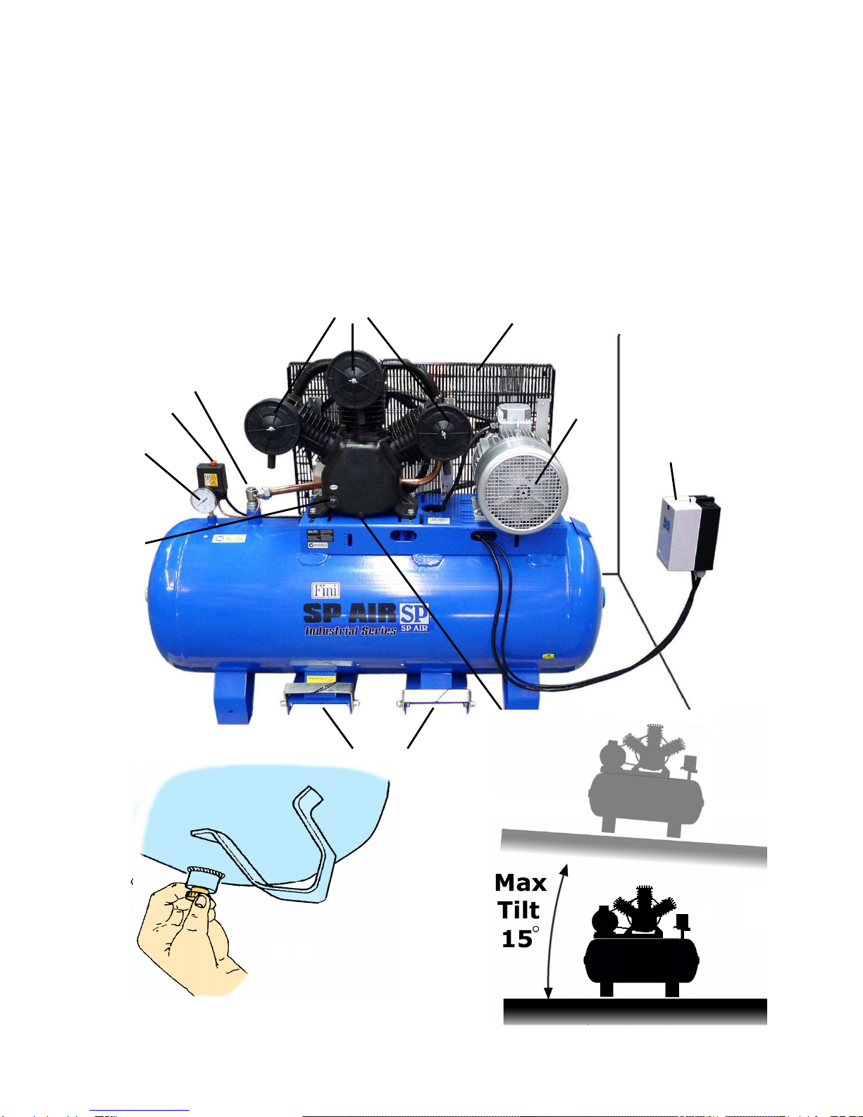
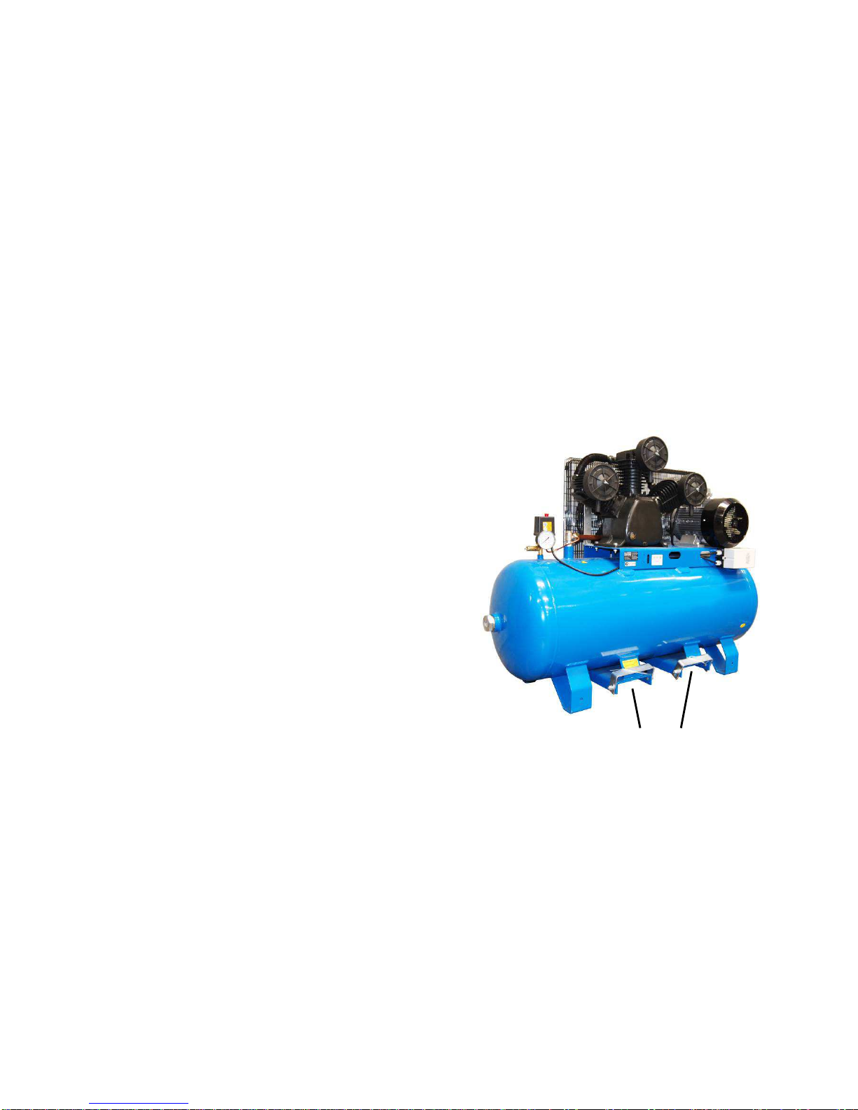
Your air compressor is a single stage, oil lubricated, and air cooled reciprocating air compressor. It is t picall
supplied as a compact, self-contained, air receiver (tank) mounted unit that is automaticall regulated and driven b
a 3 phase electric motor.
The compressor is intended to provide compressed air in a multitude of applications, for example, to power
pneumatic tools, operate air dusters and spra guns, inflate tires, and suppl air for pneumatic valves and actuators.
It is commonl used as the primar source of compressed air for home garages, workshops, service stations, t re
shops, factories, farms, mobile service vehicles, and so on. Supplementar duties can include furnishing
compressed air at an isolated location not serviced b the regular shop air s stem, and standb service when
larger compressors are shut down.
Air discharged from an oil lubricated compressor t picall contains small amounts of oil, water and particulates
amongst other contaminants. Virtuall all applications require treatment of the compressor’s output air to make it
suitable for the end use. Air qualit treatments such as filtration and dr ing are the most common requirements
together with pressure regulation. The use of compressed air lubricators to protect pneumatic tools is also
commonplace nowada s. Failing to install appropriate compressed air treatment equipment will likel result in
damage to pneumatic machiner or spra painted finishes.
Where installed, compressed air filtration and/or dr ing equipment should be located downstream from the air
receiver tank and ahead of an pressure regulator. Lubricators, on the other hand, should be installed as the last
stage of treatment and located behind or downstream from an pressure regulator.
FUNCT ON
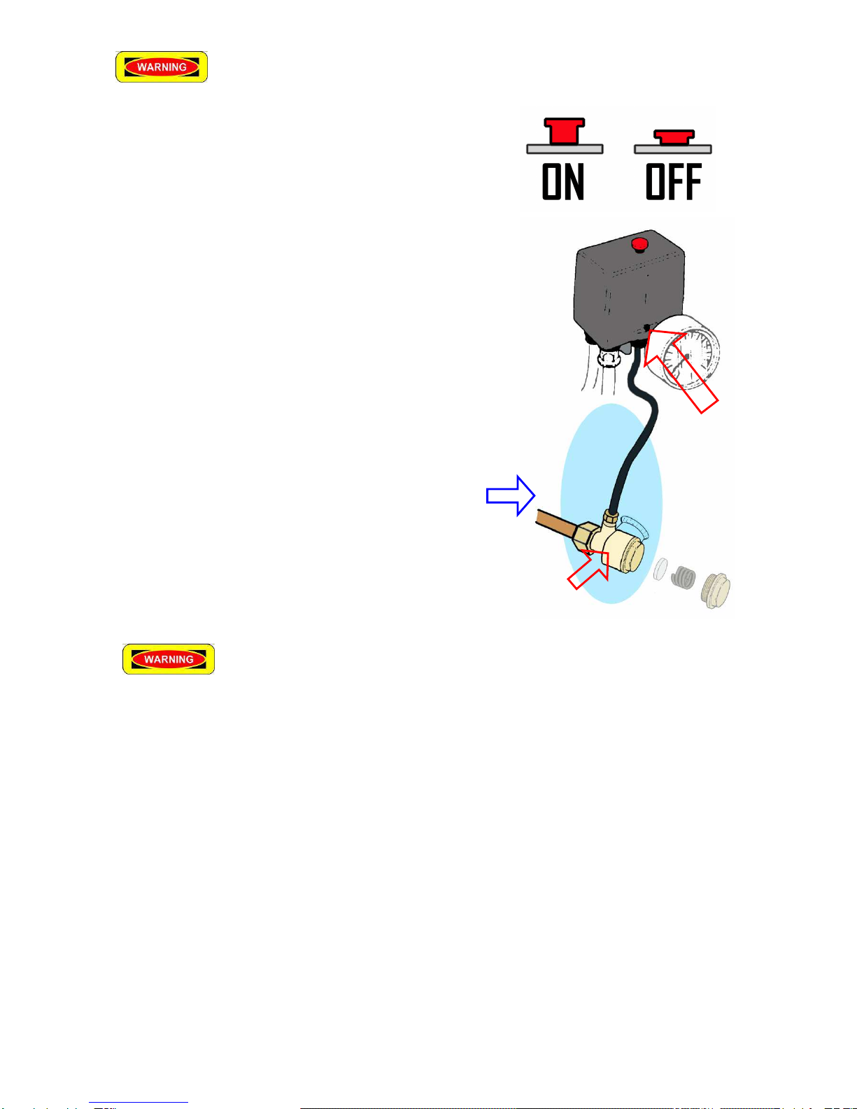
The pressure switch turns on the motor when the air receiver tank is at or below the minimum “cut-in” pressure.
The compressor then runns until the tank pressure reaches the maximum “cut-out” pressure whereupon the
pressure switch turns the motor off. Air will then be heard (for some seconds), escaping from the unloader valve
(in the base of the pressure switch) releasing residual air pressure in the discharge pipe and on top of the pistons in
the compressor pump. Thereb allowing the compressor to re-start easil , when next required.
The pressure switch is factor preset with cut-in and cut-out pressures of approximatel 120 psi and 150 psi,
respectivel . This range is ideal for the vast majorit of compressed air applications as most pneumatic tools have
been designed for use with a suppl (line pressure) of 90 psi. (6bar). Unless necessar for a special application,
line pressures of more than 90 psi. (6bar) are not recommended.
In the event that a pressure switch were to fail to turn the motor off at the prescribed cut-off pressure, then the
safet valve will protect the air receiver tank against over pressurizing b automaticall releasing air when the
pressure exceeds its preset value (ie 150psi [10bar]) . Air receiver tanks are designed and manufactured to
satisf the requirements of Australian Standards and all Australian Occupational or Workplace Health and Safet
Regulations.