
Spa Guts CY6230H Manuale utente

6230Y SERIES
OWNERS OPERATION GUIDE



1
CONTENTS
Error Indication.......................................................................................11
TROUBLESHOOTING.............................................................................12-13
Notes.......................................................................................................14
Operation Considerations.......................................................................9-10
Important Safety Instructions................................................................2-3
Intgroduction/Major Component Illustration........................................4
SYSTEM OPERATION
Power-Up / Breaker Settings.................................................................5
Spaside Operation...................................................................................6-7
Filtration Programming............................................................................8
Spa Light...................................................................................................9
ŸWinterizing
ŸChemical Water Treatment
ŸWarm Weather Conditions
ŸFiltration System
Warranty Information.............................................................................15

2
WARNING - RISK OF CHILD DROWNING. Extreme caution must be exercised to
prevent unauthorized access by children. To avoid accidents, ensure that
children cannot use a spa or hot tub unless they are supervised at all times.
DANGER To reduce the risk of injury, do not permit children to use this product
unless they are closely supervised at all times.
Prolonged immersion in water that is warmer than normal body temperature can
result in a dangerous condition known as HYPERTHERMIA. The causes,
symptoms, and effects of hyperthermia may be described as follows:
Hyperthermia occurs when the internal temperature of the body reaches a level
several degrees above the normal body temperature of 98.6BF. The symptoms
of hyperthermia include dizziness, fainting, drowsiness, lethargy, and an
increase in the internal temperature of the body. The effects of hyperthermia
include (1) unawareness of impending hazard, (2) failure to perceive heat, (3)
failure to recognize the need to exit spa, (4) physical inability to exit spa, (5)
fetal damage in pregnant women, (6) unconsciousness resulting in danger of
drowning. WARNING The use of alcohol, drugs or medication can greatly
increase the risk of fatal hyperthermia in hot tubs and spas.
Bond accessible metal to the dedicated connector on the equipment grounding bus,
bond the equipment ground bus to the local common bonding grid as part of
the installation in the form of (1) a reinforced concrete slab for support, (2) a
ground plate provided beneath the hot tub or spa, or (3) a permanent ground
connection that is acceptable to the local inspection authority.
Spa location must accommodate sufficient drainage of water around the base of the
structure, as well as the power source compartment.
A pressure wire connector is provided on the control box to permit connection of a
solid copper bonding conductor between this point and any equipment, metal
enclosures of electrical equipment, metal water pipe, or conduit within 5 feet
(1.5m) of the unit as needed to comply with local requirements.
DANGER RISK OF ELECTRICAL SHOCK. Do not permit any electrical appliance,
such as a light, telephone, radio, or television, within 5 feet (1.5m) of a spa or
hot tub.
To reduce the risk of injury:
The water in a spa or hot tub should never exceed 104BF (40BC). Water
temperatures between 100BF (38BC) and 104BF (40BC) are considered safe for a
healthy adult. Lower water temperatures are recommended for extended use
(exceeding 10-15 minutes) and for young children.
DANGER - RISK OF ELECTRICAL SHOCK. Install at least 5 feet (1.5m) from all
metal surfaces. (A spa may be installed within 5 feet of metal surfaces if each
metal surface is permanently connected by a solid copper conductor attached to
the wire connector on the terminal box that is provided for this purpose. Refer
to NEC and local codes in effect at the time of installation.)
DANGER To reduce the risk of injury to persons, do not remove suction fittings.
Excessive water temperatures have a high potential for causing fetal damage during
the early months of pregnancy. Pregnant or possibly pregnant women should
limit spa or hot tub water temperatures to 100BF(38BC).
IMPORTANT SAFETY INSTRUCTIONS
READ AND FOLLOW ALL INSTRUCTIONS
!
!
!
!
!

3
For Cord and Plug Connected Units
Persons suffering from obesity or with a medical history of heart disease, low or high blood
pressure, circulatory system problems, or diabetes should consult a physician before
using a spa or hot tub.
The use of alcohol, drugs, or medication before or during spa or hot tub use may lead to
unconsciousness with the possibility of drowning.
For Units with a GFCI (Ground Fault Circuit Interrupter)
Connect to a grounded, grounding type receptacle only. NEVER connect the spa to an
extension cord.
Before entering the spa or hot tub, the user should measure the water temperature with an
accurate thermometer.
Persons using medication should consult a physician before using a spa or hot tub since
some medication may affect heart rate, blood pressure, and circulation.
This appliance is provided with a ground-fault-circuit-interrupter located on the control box.
Before each use and with the unit operating, push the test button. The unit should
stop operating and the reset button should appear. Push the reset button. The unit
should now operate normally. If the interrupter does not perform in this manner, a
ground current is flowing indicating the possibility of electrical shock. Disconnect the
power, or unplug from receptacle, until the fault has been identified and corrected.
Do not bury the cord.
For Permanently Installed Units
The electrical supply for this product must include a suitably rated switch or circuit breaker
to open all ungrounded supply conductors to comply with Section 422-30 of the
National Electric Code, ANSI/NFPA 70 1987. The disconnecting means must be
readily accessible to the tub occupant but installed at least 5 feet (1.5m) from the tub
water.
WARNING To reduce the risk of electrical shock, replace damaged cord immediately.
For UL Listed Equipment Assemblies
For Units with Gas Heaters
A terminal marked “G” or “ground” is provided in the wiring box located inside the
equipment compartment. To reduce the risk of electric shock, connect the terminal or
connector to the grounding terminal of your electrical service or supply panel with a
continuous green insulated copper wire in accordance with National Electric Code
Table 250-95 and any other local codes in effect at the time of the installation.
WARNING - Do not install indoors. This unit uses a gas heater that requires proper
ventilation and is intended for outdoor use only.
Install at least 5 feet (1.5m) from tub water using nonmetallic plumbing. Install blower no
less than 1 foot (305mm) above the maximum water level to prevent water from
contacting electrical equipment. Install in accordance with the installation instructions.
For Permanently Installed Units not Provided with an Internal Disconnecting Method
To reduce the risk of drowning from hair and body entrapment, install a suction fitting(s)
with a marked flow rate in gallons-per-minute that equals or exceeds the flow rate
marked on the equipment assembly.

4
INTRODUCTION
Congratulations on your new purchase. This Control System is constructed of the
finest materials and assembled under the strictest quality control standards. With
proper care and maintenance your system will provide you with many years of
reliable performance.
The following pages contain information concerning the operation and care of your
system.
LIGHT CONNECTION HEATER ACTIVE
Note: Your system may differ from the photos above, although the basic operation and
configuration will be the same.

5
POWER-UP & BREAKER SETTINGS
L __
If at power-up of the system and spaside display shows the following message: , it
means that all low-level configurations have been downloaded, but no configuration
number has been chosen.
Low-Level Configuration Number Chart
Model # Prog # Pum p 1 Pum p 2 Blow er Circ Pum p CP Function
6230 10* 2 SPD 1 SPD 1 SPD NO No Circ Pum p
6230 w /CP 11 2 SPD 1 SPD 1 SPD YES Alw ays on
6230 w /Clean CP 12 2 SPD 1 SPD 1 SPD YES Thermostat Controlled
* De fault Setting
Changing System Low-Level Program Configuration
Although every system has been factory set, in certain cases when servicing or replacing a
unit in the field, it may be necessary to set a new pre-determined low-level program
configuration. Follow these simple steps to re-enter the low-level programming using the
spaside control.
Lamp test Low-level selection
Software number
8.8.8
Boot up display sequence (Each parameter is displayed for 2 seconds)
Software Revision
All the segments and
LEDs light up.
Software Part Number Revision of the Software Low-level selected
from Low-level menu
The values
displayed
by
the
system
correspond
to
0.8 of
the
maximum
amperage
capacity
of
the
GFCI.
UseUp /
Down
button
to select the
desired value. The value can be
modified
typically from10 to 48
AMP.
Then
press
Light
button to
set
breaker
rating. This
table
shows
typicalsettings
of
b
for
different
GFCI
ratings. Select
the
one
that
matches
your breaker.
GFCI b
60
Amp 48
Amp
50
Amp 40
Amp
40Amp 32Amp
30Amp 24
16Amp
98
It'simportant to
specify
the
current rating
of
the
GFCI
usedto ensure
safe and
efficient
current
management
(and
reduce
nuisanceGFCI
trippings).
Press and hold Light button
until you access the breaker
setting menu.
It’s important to specify the current rating of the GFCI used to ensure safe and efficient
current management (and reduce nuisance GFCI trippings).
20Amp
Amp
260 2
NOTE: If all installed components do not operate or only one
component can be operated at a time it may be caused by this
setting. Set breaker size accordingly to allow components to run.
Press and hold the Pump 1
key for 30 seconds
Use
the
Temp Up/Down
key tochoose
the
new
desired low-level
configuration
number
and
press the Light key to confirm the selected configuration (referto
the configuration selectionchart below).
The spaside
display
will
show
L##
where
“##" represents the previous
configuration number registered in the system.
If the Light key is not pressed within 25 seconds, the unit will exit this menu
without changing any settings.
98
Note: DO NOT let off the button
until 30 seconds has passed and
L## is displayed. You will see
other values displayed prior that
are to be ignored during this
programming process.

6
SPASIDE CONTROL OPERATION
Pump 1 - Press o nce to turn on low speed. Press a second time to turn pump to high
(with a dual-speed pump). A third time turns pump off.
The “Pump 1” indicator lights up when Pump 1 is on. With dual-speed pump, indicator
will fl ash when Pump 1 is on at low speed.
speed
Light/Program - Press once to turn light on. Press Light key a second time to turn light off.
The “Light” indicator lights up when light is on.
Temp Up - Use Up key to raise the temperature Set Point. The temperature setting will
be displayed for 5 seconds to confirm your new selection.
Temp Down - Use Up key to lower the temperature Set Point. The temperature setting
will be displayed for 5 seconds to confirm your new selection.
up when Pump 2 is on.
The “Pump 2” indicator lights
The “Pump 3
” indicator lights up
when accessory is on.
The "Set Point" icon indicates that the display shows the
NOT the current water temperature!
desired temperature,
The "Set Point" icon indicates that the display shows the
NOT the current water temperature!
desired temperature,
Pump 1
Pump 2 /Blower Pump 3/Blower Light
Power
Temp Up
Temp Dwn
Service
Icons 1-3
Pump & Acc
Heater
ON
Set Temp
Displayed
Mode
Smart
Winter
Progress
Bar
Filtration
Indicator
Indicator
Filtration
°F/°C
AM/PM
Main Display
Time, temp, messages
Pump3/Blower - Press once to turn on accessory on, press a second will turn the
accessory off.
Pump2/Blower - Press once to turn on accessory, a second press will turn the accessory
off unless Two speed pump. Two speed pump functions as Low, High, Off
A built-in timer automatically turns the accessory off after 20 minutes unless manually deactivated
first.
A built-in timer automatically turns the accessory off after 20 minutes unless manually deactivated
first.
A built-in timer automatically turns the accessory off after 20 minutes unless manually deactivated
first.
A built-in timer automatically turns the light off after 2 hours unless manually deactivated first.
7
FEATURES & PROGRAMMING FILTRATION
LIGHT/PROGRAM Key: A long press of 5 seconds will allow you to enter the program
menu. In the program menu, the following parameters can be set: the clock, the filter
cycles or the purge cycles, the economy mode and the temperature units. While you are
in the program menu, use the up or down keys to adjust the parameters and use the
Light key jump to the next parameter.
Note: Changes will be saved after the confirmation of the last parameter only. If
there is no key press for 10 seconds, the system will exit the program menu
without saving the changes.
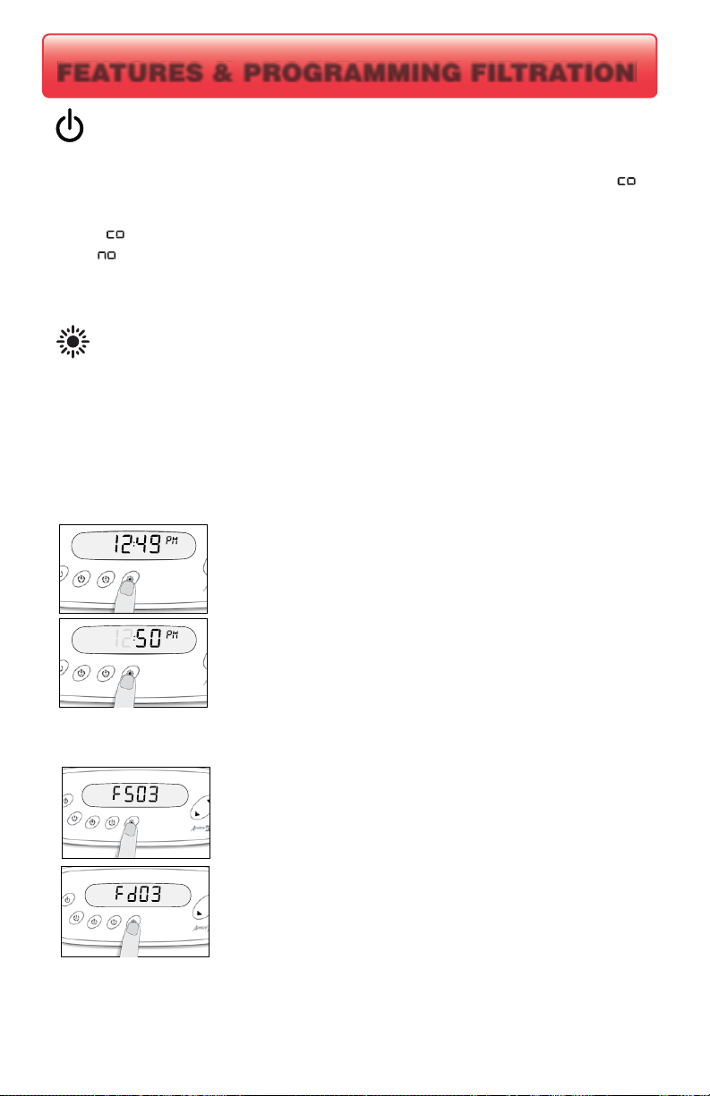
Press the LIGHT key to advance to changing the minutes
Setting the Clock: Enter the programming menu by pressing and
holding the LIGHT key for 5 seconds. The current time will be
displayed with the hours flashing.
Press the UP or DOWN key to adjust the hours accordingly making
sure the AM/PM indicator is set properly.
Press the UP or DOWN key to adjust the hours accordingly making
sure the AM/PM indicator is set properly.
0 = No Filtration
Press the UP or DOWN key to adjust the hours accordingly making
sure the PM indicator is set properly.
Setting the Filter Cycle: Enter the programming menu by pressing
and holding the LIGHT key for 5 seconds. The current time will be
displayed with the hours flashing. If adjusting the clock is necessary
do it now, otherwise press the LIGHT key repeatedly until FS## is
displayed. “FS” represents FILTER START “##” represents the
start time hour.
24 = Continuous Filtration
Press the LIGHT key until F ## is displayed. “F ” represents
FILTER DURATION “##” represents the run time for the filter
cycle.
PP
Manual Economy Mode - When active this mode forces the system to maintain a
temperature 20F° less than the set temperature, the display will toggle between “E ” the
clock and the water temperature. Press the power button again to disable economy mode.
Power Key - This key provides access to:
E = Economy mode not active
E = Economy mode active
Questo manuale è adatto per i seguenti modelli
1
Indice
Altri manuali Spa Guts Vasca idromassaggio


