
SPARENERGO SE5000U Manuale utente

User Manual
SE5000U (15S 48V-4.8Kwh /16S 51.2V-5.12Kwh)
SE7000U (15S 48V-7.2Kwh / 16S 51.2V-7.68Kwh)
SE10000U (15S 48V-9.6Kwh / 16S 51.2V-10.24Kwh)
For On / Off Hybrid Solar Storage System

Version: 1.0
Contents
1. Safety Pre autions.............................................................................................................................................. - 2 -
1.1. Before Conne ting .................................................................................................................................................. - 2 -
1.2. During operation .................................................................................................................................................... - 2 -
2. Battery Spe ifi ations
................................................................................................................................................... - 3 -
3. Introdu tion to the battery
.......................................................................................................................................... - 5 -
3.1. Key Features ........................................................................................................................................................... - 5 -
3.2. Interfa e Introdu tion ............................................................................................................................................. - 5 -
3.3. SOC Indi ator & Status Indi ator Guides.............................................................................................................. - 6 -
3.4. Conne tors.............................................................................................................................................................. - 7 -
3.5. Wake Up button........................................................................................................................................................ - 7 -
3.6. Display fun tion instru tion ..................................................................................................................................... - 7 -
3.6.1. Referen e of real figure
................................................................................................................................. - 7 -
3.6.2. S reen Display
.............................................................................................................................................. - 8 -
3.6.3. Fun tional Spe ifi ations
............................................................................................................................. - 8 -
4. Safe handling guide
.................................................................................................................................................. - 10 -
4.1. System Diagram .................................................................................................................................................... - 10 -
4.2. Tools....................................................................................................................................................................... - 10 -
4.3. Safety Gear............................................................................................................................................................. - 11 -
5. Installation
................................................................................................................................................................ - 11 -
5.1. Inventory of items ................................................................................................................................................... - 11 -
5.2. Installation Lo ation ............................................................................................................................................... - 11 -
5.2.1. Minimum learan es
.................................................................................................................................. - 12 -
5.3. Installing the Battery Pa k...................................................................................................................................... - 13 -
5.3.1. Mounting to a wall
....................................................................................................................................... - 13 -
5.4. Parallel use of battery ........................................................................................................................................... - 14 -
5.4.1. Parallel use of battery ( All off grid solar inverters )........................................................................................ - 14 -
5.4.2. Parallel use of SL battery on Canbus /RS485( All hybrid on-off grid solar inverters) ............................... - 16 -
5.4.3. ADS guide Line ............................................................................................................................................... - 17 -
6. Produ t Warranty
...................................................................................................................................................... - 24 -
6.1. ................................................................................................................................................................................ - 24 -
6.2. ................................................................................................................................................................................ - 24 -
6.3. ................................................................................................................................................................................ - 24 -
6.4. Fa tory Warranty S ope ....................................................................................................................................... - 24 -
6.5. Warranty onditions............................................................................................................................................... - 24 -

1.
Safety Pre autions
•It is very important and ne essary to read the user manual arefully before installing or using the
battery. Failure to follow any of the instru tions or warnings in this do ument an result in
ele tri al sho k, serious injury, death, or may damage the battery and the whole system.
•If the battery is stored for a prolonged time, it is requirement that they are harged every three to
six months, and the SOC should be no less than 80%.
•The battery needs to be re harged within 12 hours, after fully dis harging.
•Do not expose able outside.
•All battery terminals must be dis onne ted before maintenan e.
•Do not use leaning solvents to lean the battery.
•Do not expose the battery to flammable or harsh hemi als or vapors.
•Do not paint any part of the battery, in lude any internal or external omponents.
•Do not onne t battery with PV solar wiring dire tly.
•Any foreign obje t is prohibited to be inserted into any part of the battery.
•Any warranty laims are ex luded for dire t or indire t damage due to items above.
1.1.
Before Conne ting
•After unpa king, please he k the battery and pa king list first, if the battery is damaged or spare
parts are missing, Please onta t the dealer.
•Before installation, be sure to ut off the grid power and make sure the battery is in the turned-off
mode;
•Wiring must be orre t, do not mix- onne t the positive and negative ables, and ensure no short
ir uit with the external devi e;
•It is prohibited to onne t the battery with AC power dire tly;
•The embedded BMS in the battery is designed for 48VDC, please DO NOT onne t battery in
series;
•It is prohibited to onne t the battery with different type of battery;
•Please ensure the ele tri al parameters of battery system are ompatible to inverter;
•Keep the battery away from fire or water.
1.2.
During operation
•If the battery system needs to be moved or repaired, the power must be ut off first and the
battery is ompletely shutdown;
•It is prohibited to onne t the battery with different type of battery;
•It is prohibited to put the batteries working with faulty or in ompatible inverter;
•In ase of fire, only dry powder fire extinguisher an be used, liquid fire extinguishers are
prohibited;
•Please do not open, repair or disassemble the battery. We do not undertake any onsequen es or
related responsibility due to violation of safety operation or violating of design, produ tion and
equipment safety standards.

2.
Battery Spe ifi ations
Battery Spe ifi ations
Model No
SE-5000U/15S SE-7000U/15S SE-10000U/15S
Nominal Parameters
Voltage
48 V 48 V 48 V
Capa ity
100Ah 150Ah 200Ah
Energy
4.8 KwH 7.2 KwH 9.6 KwH
Dimensions (L x W x H)
680 x480 x180(220)mm 680 x480 x180(220)mm 680x480x180(220)mm
Weight
58.5kg 75.0 kg 96.5kg
Basic Parameters
Life time(25°C)
20 years
Life y les(80% DOD, 25°C)
6000 Cy les
Storage time / temperature
5 months @ 25°C; 3 months @ 35°C; 1 month @
45°C
Operation temperature
-20°C to 60°C @60+/-25% Relative Humidity
Storage temperature
0°C to 45°C @60+/-25% Relative Humidity
Lithium Battery Standard
IEC62619,UN38.3,ROHS,CE-
EMC,UL1642,MSDS
En losure prote tion rating
IP21
Ele tri al Parameters
Operation voltage
48 Vd 48
Vd
48 Vd
Max. harging voltage
54 Vd 54
Vd
54 Vd
Cut-off Dis harge Voltage
42 Vd 42
Vd
42 Vd
Max. harging and
dis harging urrent
100A(4800W) 120A(5760W) 120A(5760W)

Battery Spe ifi ations
Model No
SE-5000U/16S SE-7000U/16S SE-10000U/16S
Nominal Parameters
Voltage
51.2V 51.2V 51.2V
Capa ity
100Ah 150Ah 200Ah
Energy
5.12KwH 7.68KwH 10.24KwH
Dimensions (L x W x H)
680 x480 x180(220)mm 680 x480 x180(220)mm 680x480x180(220)mm
Weight
60.50kg 78.0 kg 105.5kg
Basic Parameters
Life time(25°C)
20 years
Life y les(80% DOD, 25°C)
6000 Cy les
Storage time / temperature
5 months @ 25°C; 3 months @ 35°C; 1 month @
45°C
Operation temperature
-20°C to 60°C @60+/-25% Relative Humidity
Storage temperature
0°C to 45°C @60+/-25% Relative Humidity
Lithium Battery Standard
IEC62619,UN38.3,ROHS,CE-
EMC,UL1642,MSDS
En losure prote tion rating
IP21
Ele tri al Parameters
Operation voltage
51.2 Vd 51.2 Vd 51.2 Vd
Max. harging voltage
58 Vd 58 Vd 58 Vd
Cut-off Dis harge Voltage
44 Vd 44 V d 44 Vd
Max. harging and
dis harging
urrent
100A(5120W) 120A(6144W) 120A(6144W)
3.
Introdu tion to the battery
3.1.
Key Features
•LiFePO4 omposition – provides ex eptional safety and longevity
•High safety and reliability
•6,000 y les/20 year servi e life
•Consistent performan e over wide temperature range
•Wall-mounted, onvenient installation
•Integrated state-of-the-art BMS to manage and monitor battery information in luding voltage,
urrent and temperature as well as balan e ell harging/dis harging rates
•5-10years warranty
3.2.
Interfa e Introdu tion
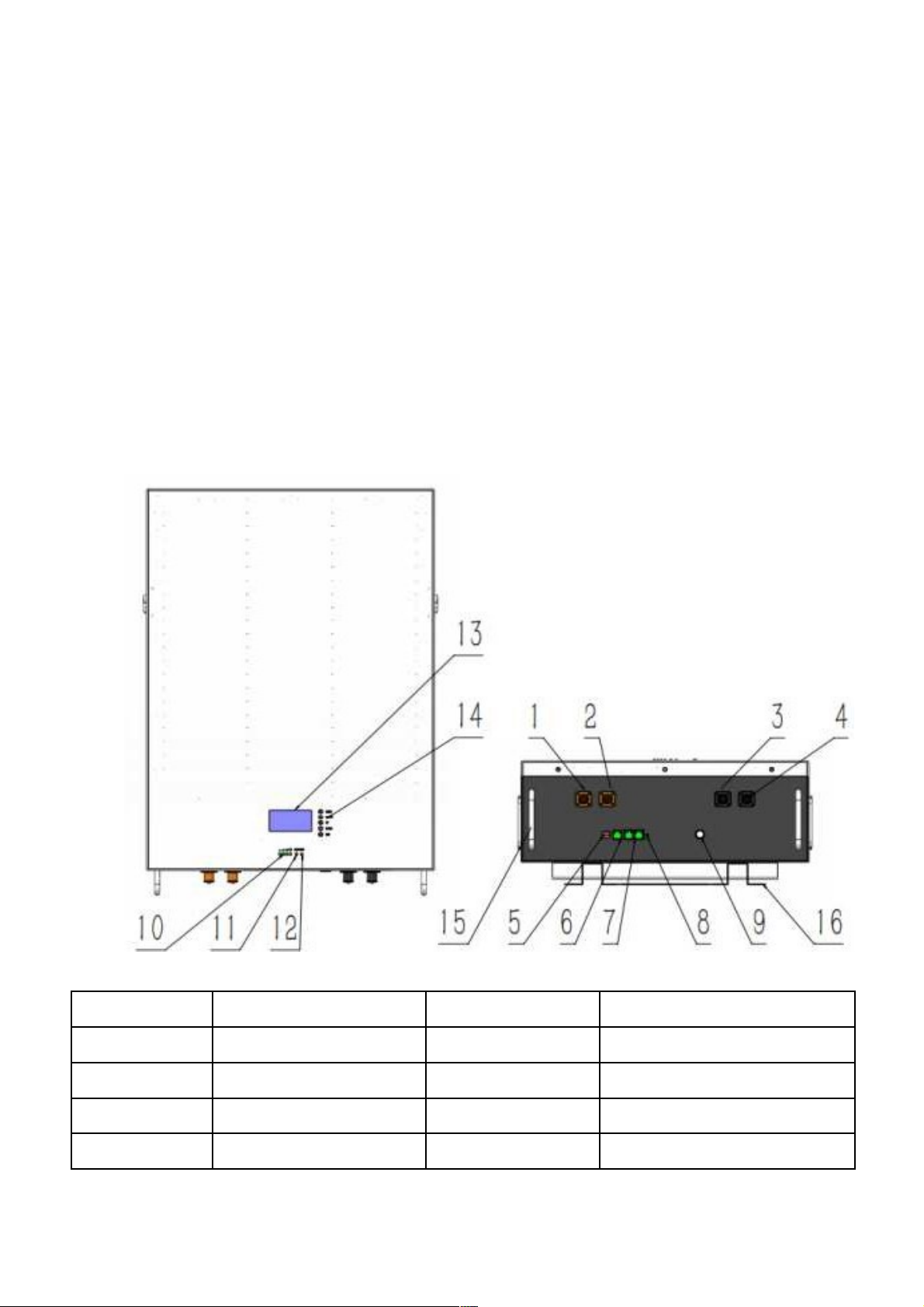
•This se tion details the interfa e fun tions of front and ba k panel..
•Front interfa e:
•No. •Des ription •Silk-s reen •Remark
•1-2 •UES0600 •P+ P+ •Output terminal
•3-4 •UES0600 •P- P- •Output terminal
•
5
•Dial swit h •ADS •Set the address
•
6
•Canbus •Canbus •Canbus ommuni ation port

•
7
•RS485 port •RS485 •RS485 ommuni ation port
•
8
•port Reset button •RST •For reset the batter
•
9
•Battery Swit h •On/Off •Turn On/Off
•10 •LED •CAPACITY •Capa ity indi ator
•11 •LED •ALM •Alarm indi ator
•12 •LED •RUN •Operation indi ator
•13 •LCD
• •
•14 •LCD Key
• •
•15 •Handle
• •
•16 •Bra ket
• •

3.3.
SOC Indi ator & Status Indi ator Guides
•Chart 1: Battery Status
Normal/
RUN
ALM Capa ity LED
Status
Warning/
Prote tion
Description
Shut
Down
Shut down OFF OFF OFF OFF OFF OFF All OFF
Standby
Normal Flash OFF OFF OFF OFF OFF Standby
Charge
Normal ON OFF
Based on apa ity
Warning ON Flash
Prote tion ON ON
Dis harge
Normal ON OFF Based on apa ity
Warning ON Flash
Prote tion OFF ON OFF OFF OFF OFF UVP, OCP…
Fault
Prote tion OFF ON OFF OFF OFF OFF Stop harging
or dis harging
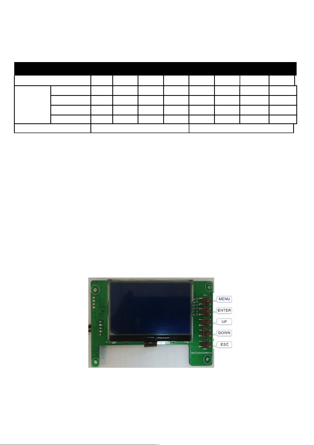
•Chart 2: Battery Capa ity
Status Charging
Dis harging
Capa ity LED Indi ator
~
L4 L3 L2 L1 L4 L3 L2 L1
Capa ity
0 25%
~
OFF OFF OFF Flash OFF OFF OFF NO
25 50%
~
OFF OFF Flash ON OFF OFF NO NO
50 75%
~
OFF Flash ON ON OFF NO NO NO
75 100% Flash ON ON ON NO NO NO NO
RUN Status
NO Flash
3.4.
Conne tors
Charge / Dis harge onne tors: to onne t the positive pole (+) and negative pole (-) from the battery
to the inverter via DC isolator.
Canbus/ RS485: A tive ommuni ation portal between battery and inverter.
USB To RS232: to get dynami monitoring data of the battery from upper omputer.
Address: Reserved Address portal for multiple parallel onne tions.
3.5.
Wake Up button
•Battery On: When battery is shut down, press this RST button for 3 se onds. It is a tivated
when the LED lights fli ker from RUN light to the lowest apa ity indi ator.
•Battery off: When battery is a tivated, press this button for 3 se onds. It will be shut down
when the LED lights fli ker from lowest apa ity indi ator to RUN light.
3.6.
Display fun tion instru tion
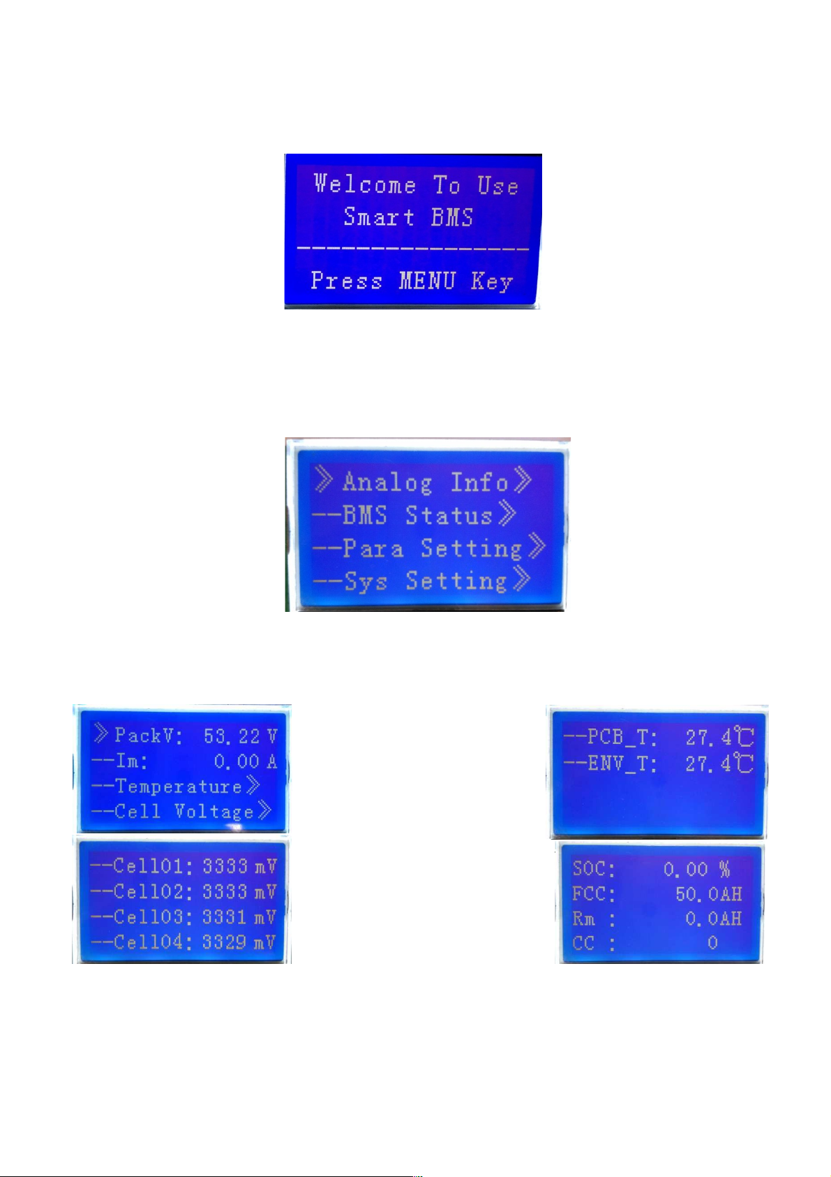
3.6.1.
Referen e of real figure
3.6.2.
S reen Display
3.6.3.
Fun tional Spe ifi ations
•Interfa e introdu tion
•Main menu page
•Ele tri ity/dorman y a tivated, will show the wel ome s reen, press the MENU button to enter
the main menu page. As shown in the figure below:
•Battery parameters olle tion page
When the ursor“》”is point to “Battery Parameters A quisition”,press ENTER key will enter
into the page of“Battery Parameters A quisition”,As shown in the figure below:
Questo manuale è adatto per i seguenti modelli
5
Indice


