sparkfun Qwiic APA102C Documento tecnico

Qwiic LED Stick - APA102C Hookup Guide
Introduction
The SparkFun Qwiic LED Stick - APA102C simplifies adding addressable LED control to any I C project using the
SparkFun Qwiic System. The board includes 10 APA102 addressable LEDs controlled by an ATTiny85 on the
board to work in tandem with either the SparkFun Qwiic LED Stick Arduino library or Python package..
2
SparkFun Qwiic LED Stick - APA102C
COM-18354
Product Showcase: SparkFun Qwiic LED StickProduct Showcase: SparkFun Qwiic LED Stick

The Qwiic LED Stick was designed with making large chains of them in mind so with a quick software command,
you can change the I C address of the ATTiny85 so you can control up to 100 LEDs (10 Qwiic LED Sticks) on a
single bus! Now, having a hundred LEDs in a circuit significantly increases the required current to drive them and
regulators on most development boards are limited to a few hundred mA so we've designed the Qwiic LED Stick to
adjust the power input so a dedicated power supply can be used to drive the LED Sticks.
In this tutorial we'll cover the hardware present on the Qwiic LED Stick, how to assemble a basic circuit and to top
it off we'll take a close look at the SparkFun Qwiic LED Stick Arduino library and Python package as well as a few
of the examples included in them.
Required Materials
In order to follow along with this tutorial you'll need a few items along with the Qwiic LED Stick.
First off, the Qwiic LED Stick needs a controller like an Arduino development board or single-board computer
(SBC) like a Raspberry Pi to communicate with the board. Click the button below to toggle to recommended
Raspberry Pi and Qwiic Pi products.
RASPBERRY PI MATERIALS (TOGGLE)
Below are a few Arduino development boards SparkFun carries that are Qwiic enabled out of the box:
2
SparkFun Qwiic Pro Micro - USB-C
(ATmega32U4)
DEV-15795
SparkFun RedBoard Qwiic
DEV-15123
SparkFun RedBoard Artemis
DEV-15444
SparkFun Qwiic Micro - SAMD21 Development
Board
DEV-15423

If your preferred microcontroller does not have a Qwiic connector, you can add one using one of the following
products:
Along with a development board or SBC, you'll need at least one Qwiic cable. SparkFun carries a variety of
lengths and types of Qwiic cables as seen here:
SparkFun Qwiic Adapter
DEV-14495
SparkFun Qwiic Shield for Arduino
DEV-14352
SparkFun Qwiic Shield for Thing Plus
DEV-16790
SparkFun Qwiic Shield for Arduino Nano
DEV-16789
SparkFun Qwiic Cable Kit
KIT-15081
Qwiic Cable - 100mm
PRT-14427

Recommended Tools
If you plan to use multiple Qwiic LED Sticks in your project, a few other tools and hardware are needed to
assemble and drive your circuit. You may already have some of the products and tools suggested below so adjust
your selections as needed.
As mentioned above, using many Qwiic LED Sticks draws a significant amount of current that your microcontroller
may not be able to provide. We recommend using a dedicated power supply for the APA102 LEDs on the LED
Stick. Select your power supply based on the estimated total current draw of the LEDs in your circuit. Below are a
few options that can work with the APA102 LEDs:
Qwiic Cable - 200mm
PRT-14428
Flexible Qwiic Cable - 100mm
PRT-17259
Power Supply - 5V, 4A
TOL-15352
SparkFun Breadboard Power Supply 5V/3.3V
PRT-00114
Power Supply - 12V/5V (2A)
TOL-15664
Mean Well LED Switching Power Supply -
5VDC, 5A
TOL-14601

Along with a dedicated power supply, you may need some tools to solder with. If you need a soldering iron or
soldering supplies, take a look at the tools and supplies below:
Recommended Reading
In case you are not familiar with the Qwiic System, we recommend reading here for an overview:
We also recommend taking a look at the following tutorials if you aren't familiar with the concepts covered in them:
Soldering Iron - 60W (Adjustable Temperature)
TOL-14456
Solder - 1/4lb Spool (0.020") Special Blend
TOL-10242
Solder Lead Free - 100-gram Spool
TOL-09325
Weller WLC100 Soldering Station
TOL-14228
How to Power a Project
Logic Levels

Hardware Overview
The Qwiic LED Stick is a fairly straightforward ATTiny85-based Qwiic board that you may be familiar with already.
In this section we'll cover the hardware present on the board in detail.
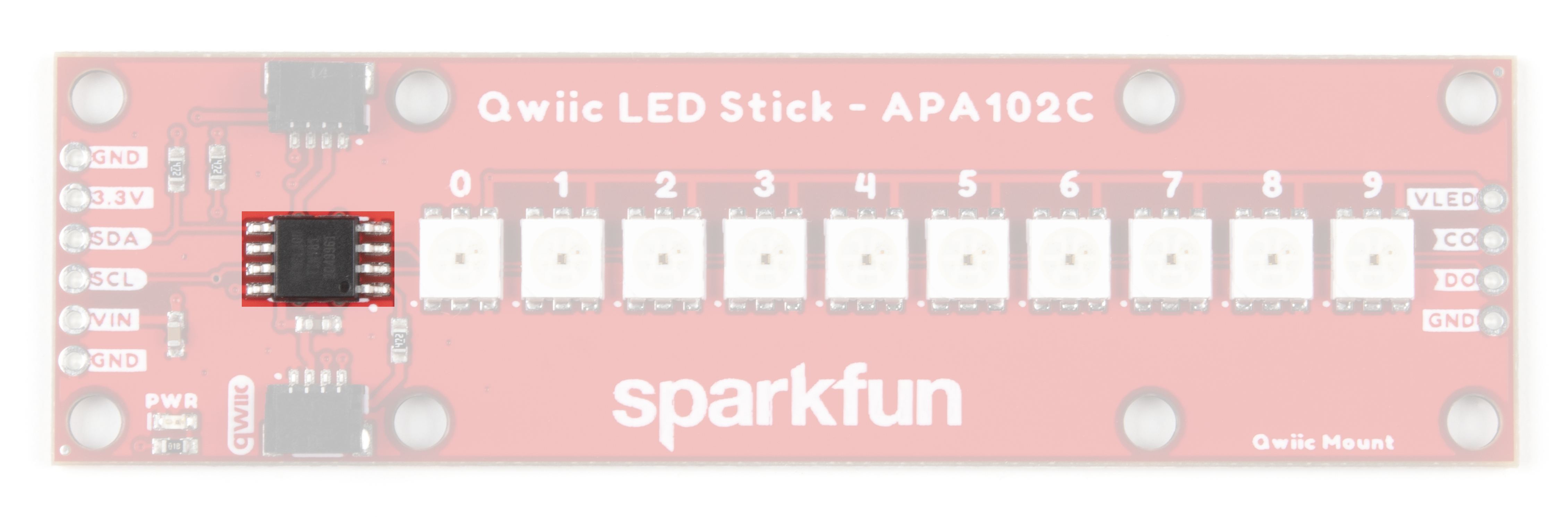
ATTiny85
The brains of the Qwiic LED Stick is one of our favorite microcontrollers, the ATTiny85. This IC comes pre-
programmed with custom firmware designed to interact with the Arduino library and Python package we've written
to use with this board. The ATTiny85 accepts I C reads and writes, interprets them and outputs the appropriate
strings to control any APA102 LEDs attached to it.
The default I C address of the ATTiny85 is 0x23. Adjust the address either through the ADR jumper or via
software. Read on for more information regarding changing the address in both manners.
Just like our other Qwiic breakouts using the ATTiny85, users can update or change the firmware using the 2x3 pin
header on the back of the board. The firmware can be found in the Hardware GitHub Repository. For tips and
tricks on how to re-program an ATTiny IC, check out this tutorial.
APA102C LEDs
The LED Stick includes 10 APA102C LEDs controlled by the aforementioned ATTiny85. APA102C LEDs operate
just like most addressable LEDs over a two-wire interface. The board ties that interface to the ATTiny85 and
operates both the IC and LEDs at 3.3V logic. For specific information regarding the LEDs, take a look at the
APA102C Datasheet.
A tutorial to help figure out the power requirements of
your project.
Learn the difference between 3.3V and 5V devices and
logic levels.
I2C
An introduction to I2C, one of the main embedded
communications protocols in use today.
Serial Terminal Basics
This tutorial will show you how to communicate with
your serial devices using a variety of terminal emulator
applications.
2
2

The board includes a dedicated power PTH pin labeled VIN (along with a spare Ground PTH) to power the LEDs
directly for longer chains of Qwiic LED Sticks or circuits with an extra LED strip that require more power than a
typical microcontroller can provide. Enable this power input by adjusting the VLED jumper. The APA102C LED
accepts a supply voltage between 3.0V and 5.5V.
We've also routed the LED control signals out to a dedicated 0.1"-spaced PTH header on the edge of the board in
case you would like to add another APA102 LED strip to the end of the LED stick. This PTH header has signal
labels as well as silk labels on the bottom of the board for the coordinating wire colors (Red, Blue, Green and
Yellow) to make it easy to match the wires for standard APA102 LED strips.
Qwiic and I C Interface
As the product name suggests, the LED Stick routes the I C interface on this board to a pair of Qwiic connectors
for easy assembly using the Qwiic system. Those who prefer a a traditional soldered connection for the circuit can
use the I C pins routed to a standard 0.1"-spaced PTH header.
3.3V and GND are also provided via the Qwiic interface to power both the ATTiny85 as well as the APA102C LEDs
in the default configuration.
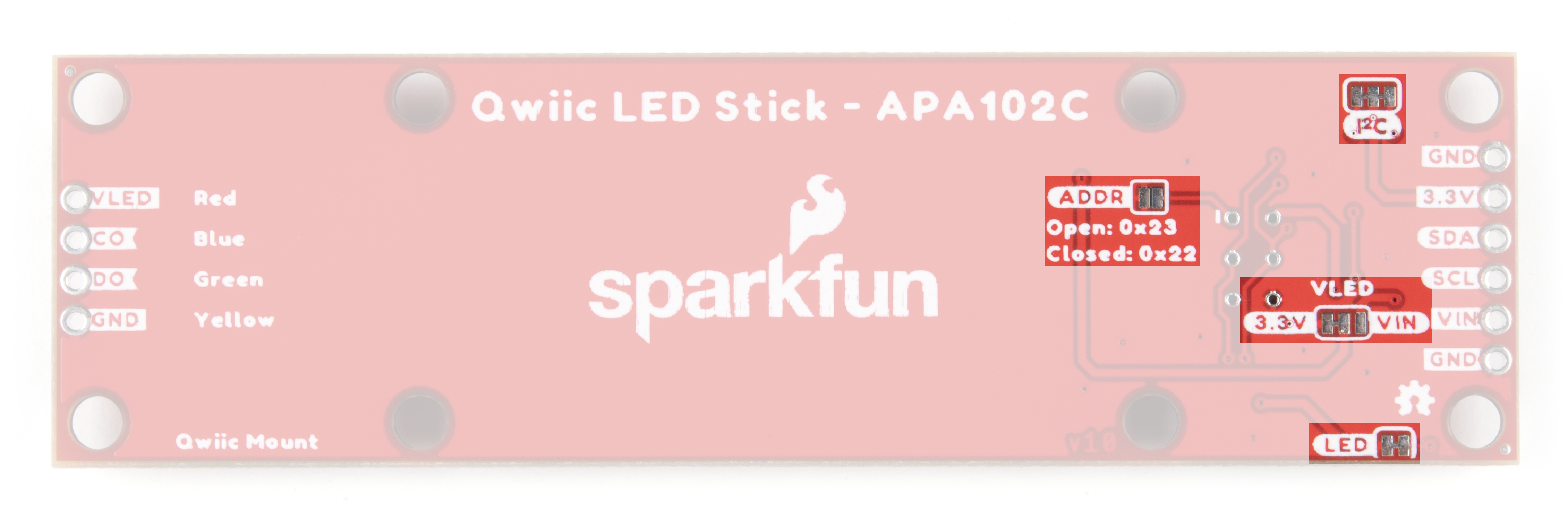
Solder Jumpers
The Qwiic LED Stick has four solder jumpers labeled I2C, VLED, ADR and LED. Let's take a closer look at them
and their functionality. If you've never worked with solder jumpers before or would like a refresher, take a look at
our How to Work with Jumper Pads and PCB Traces tutorial.
The I C jumper pulls the SDA/SCL lines on the ATTiny85 to 3.3V via a pair of 4.7kΩ resistors. Disable these pull
up resistors by severing the trace between the three pads. Recommended practice is to only have a single pair of
pull up resistors enabled on an I C bus to avoid communication errors caused by too strong of a parallel
resistance. If you are using multiple Qwiic LED Sticks or other I C devices in a long chain, we recommend
disabling all but one of these resistor pairs.
The VLED jumper controls the input voltage for the APA102C LEDs. By default, this two-way jumper ties the
APA102C VCC to 3.3V provided either over the Qwiic connector or the labeled PTH pin. For long chains of Qwiic
LED Sticks, switch this jumper to the VCC side by severing the trace between the center and 3.3V pad and adding
2
2
2
2
2
2

a blob of solder to connect the center pad with the VCC side. Once this is adjusted, connect a separate voltage
between 3.0V and 5.5V to the VIN PTH pin to power the circuit. When in the VIN position, the board connects a
4.7µF decoupling capacitor to help smooth out power supplied to the LEDs.
Note: The VLED jumper isolates the voltage input from the 3.3V used to power the ATTiny85. When using
the VIN PTH pin to power the LEDs, make sure to provide power to the ATTiny85 either via the Qwiic
interface or over the 3.3V PTH pin.
The ADR jumper sets the I C address of the ATTiny85 via a hardware adjustment and is OPEN by default. While
open, the ATTiny85's address is set to 0x23. Closing this jumper adjusts the address to 0x22.
The LED jumper controls the board's power LED by tying the anode to 3.3V via a 1kΩ resistor. The jumper is
CLOSED by default. Sever the trace between the two pads to disable the power LED if needed.
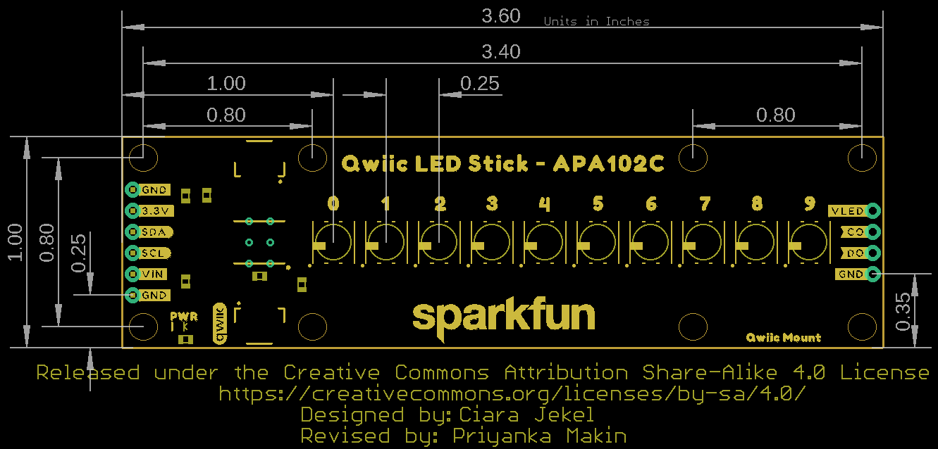
Board Dimensions
The Qwiic LED Stick measures 1.00in x 3.60in (25.4mm x 91.44mm) with four mounting holes that fit a 4-40
screw.
Hardware Assembly
Assembling a basic Qwiic LED Stick circuit is easy with the Qwiic system so we'll cover that assembly as well as a
few things to be aware of when assembling a larger string of Qwiic LED Sticks or when using other APA102Cs on
the end of the stick.
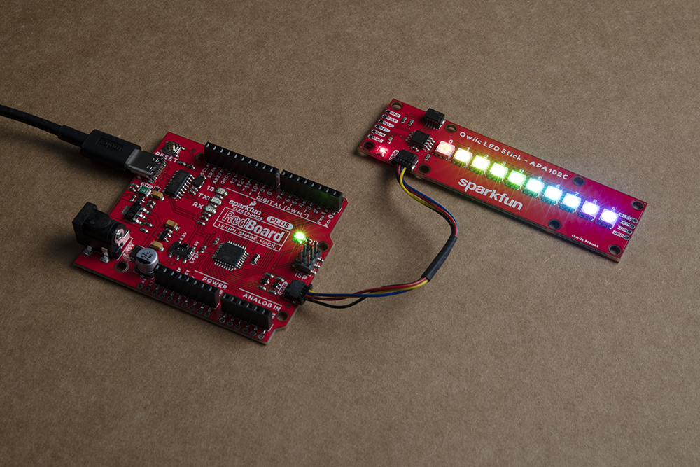
Basic Qwiic/I C Assembly
For a basic Qwiic LED Stick circuit with a board like the SparkFun RedBoard Qwiic Plus all you need to do is plug
the two boards together with a Qwiic cable.
Multiple Qwiic LED Sticks and APA102C Extensions
2
2

Users who wish to use multiple Qwiic LED Sticks chained together or even with an external APA102C LED Strip
connected to the LED PTH header on the side of the board will need to do some minor soldering assembly as well
as adjusting solder jumpers.
First, take into account the max current draw the LED Stick chain will pull. At full power, each APA102C can draw
as much as 40mA when set to white (full Red, Green and Blue) at full brightness so we recommend testing the
current draw of your LED chain prior to wiring up long chains of LED Sticks (or adding an extra LED strip) to avoid
damaging your controller. In our testing, while running all 10 LEDs at full brightness and White color, the strip only
pulled [email protected] so you should be safe powering a few of these from your microcontroller but note that most
Qwiic development boards use a 3.3V/600mA regulator to power devices connected to the Qwiic connector.
For detailed assembly instructions and tips for building APA102 LED circuits, take a look at our APA102
Addressable LED Hookup Guide:
APA102 ADDRESSABLE LED HOOKUP GUIDE - HARDWARE ASSEMBLY
If using a separate power supply to power the LEDs, adjust the VLED jumper to the VIN side and connect a supply
voltage between 3.0 to 5.5 to the VIN and GND pins capable of supplying enough current to power the LED chain.
After making your power supply connections, plug the Qwiic LED Stick to the controller using a Qwiic cable or the
I C PTH pins.
Now that our Qwiic LED Stick circuit is assembled, let's take a look at the software packages we use to control
them over I C.
Qwiic LED Stick Arduino Library
Note: This library assumes you are using the latest version of the Arduino IDE on your desktop. If this is your
first time using Arduino, please review our tutorial on installing the Arduino IDE. If you have not previously
installed an Arduino library, please check out our installation guide.
The SparkFun Qwiic LED Stick Arduino Library makes controlling the LED stick as easy as sending the command
setLEDColor() with three RGB values to set the color along with a host of other functions to control the LED
Stick. Install the library by searching for "SparkFun Qwiic LED Stick" in the Arduino Library manager. Users who
prefer to manually install it can get the library from the GitHub Repository or download the ZIP by clicking the
button below:
SPARKFUN QWIIC LED STICK ARDUINO LIBRARY (ZIP)
Library Functions
The list below outlines all the functions available in the Qwiic LED Stick library along with quick descriptions of
what they do.
Class
Construct the LED object in the global scope. The examples use LEDStick as the Qwiic LED Stick object.
LED LEDStick;
Device Setup and Settings
2
2

bool begin(uint8_t address, TwoWire &wirePort); - Initialize the LED Stick at a specified address on a
chosen port. If left empty, default address will be used and Wire is used.
bool isConnected(); - Check if the LED Stick is connected to the port at the specified address.
LED Control
bool setLEDColor(uint8_t number, uint8_t red, uint8_t green, uint8_t blue); - Sets the color of the
selected LED using RGB values between 0 and 255. If no LED is selected, all LEDs are set to the specified
color. For example, to set the fourth LED to yellow the command would be LEDStick.setLEDColor(4, 0,
255, 255); .
bool setLEDBrightness(uint8_t number, uint8_t brightness); - Sets the brightness of the selected
LED. If no LED is selected, all LEDs are adjusted. Acceptable values are 0 to 31. Setting an LED to 0 will
turn it off but saves the stored color value.
bool LEDOff(void); - Sets all LEDs in the Qwiic LED Stick to off.
bool changeAddress(uint8_t newAddress); - Change the I C address of the ATTiny85. Enter a valid
address. Note once the address is changed, the LED Stick must be initialized with the new address. For
example, initialize a Qwiic LED Stick with the address 0x70 using LEDStick.begin(0x70); .
bool changeLength(uint8_t newLengths); - Change the number of LEDs in the chain. Used when adding
another Qwiic LED Stick or other addressable LED strip to the circuit. Default value is 10. Max value is 100.
Arduino Examples
The Qwiic LED Stick Arduino Library includes eleven examples to get you started with the basics of the board
along with some nifty lighting demos. In this section we'll look at a few of the examples and explore how they work.
Before we get into the examples, let's take a closer look at the setup used for all the examples. The code initializes
both the serial and wire ports as well as starts communication with the LED Stick over I C:
Wire.begin();
Serial.begin(115200);
if (LEDStick.begin() == false){
Serial.println("Qwiic LED Stick failed to begin. Please check wiring and try again!);
while(1);
}
You can open the Arduino serial monitor with the baud set to 115200 to view any serial printouts from the code. If
the Qwiic LED Stick fails to initialize on the bus at the default address, the code freezes. The two most common
causes of this is a bad connection between the device and controller or the Qwiic LED Stick's I C address does
not match the default value.
Example 1 - Blink
This basic example shows how to initialize the LED Stick along with controlling the LEDs on it all at once. Open
the example by navigating to File > Examples > SparkFun Qwiic LED Stick Arduino Library >
Example01_Blink. After opening the example, select the correct Board (in our case the SparkFun RedBoard) and
Port it enumerated on. Next, click upload and barring any errors, you should see all ten LEDs set to the same color
(white) and turn on and off every second.
Try adjusting the values in this line to change the color:
2
2
2
Questo manuale è adatto per i seguenti modelli
1
Indice


