sensitive to loading, it’s internally buffered with a JFET (junction field-effect transistor).
Due to the mechanical and electronic tolerances involved, some capsules are more sensitive than others. Also, the
JFET is rather sensitive to noise on the power supply. Both of these factors need to be accounted for when
deploying the Sound Detector.
Power Supply
The Sound Detector is an analog circuit, and as such, it’s more sensitive to noise on the power supply than most
digital circuits. Since the capsule is effectively a voltage divider sitting across the power rails, it will transcribe any
noise on the supply lines onto the capsule output. The next circuit in the chain is a high-gain amplifier, so any
noise on the supply will then be amplified. Therefore, the Sound Detector may require more careful power supply
configuration than many circuits.
In testing with various supplies, a significant degree of variability was discovered - some supplies are less noisy
than others. One exhibited as much as 30 mV ripple on the supply output, an as a result, the the Sound Detector
was rather sensitive and unstable. You can check how clean a power supply is by checking it with an oscilloscope
or volt meter, set to the AC Volts (or, if provided, the AC millivolts) range. A truly clean supply will show 0.000 VAC.
Based on the supplies used in testing, ripple of more than about 10 mV is problematic.
Powering my Arduino with a 9V external supply, which allows the onboard regulators to function, the Arduino’s 5V
output was sufficiently clean. However, powering it from the 5V available on the USB port on a PC, the regulators
are bypassed, and the results were somewhat less usable, and vary greatly between different ports on different
PCs. A powered USB hub will probably provide cleaner power than the ports on the PC itself.
If all else fails, three 1.5V batteries in series make a nice, clean source of 4.5V.
Amplitude Calibration
The Sound Detector comes set for moderate sensitivity - speaking directly into the microphone, or clapping your
hands nearby should cause the gate output to fire. If you find that it doesn’t work well in a specific application, you
can change the circuit to be more or less sensitive.
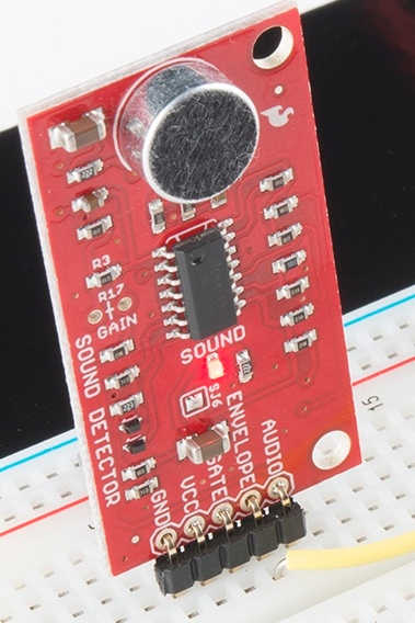
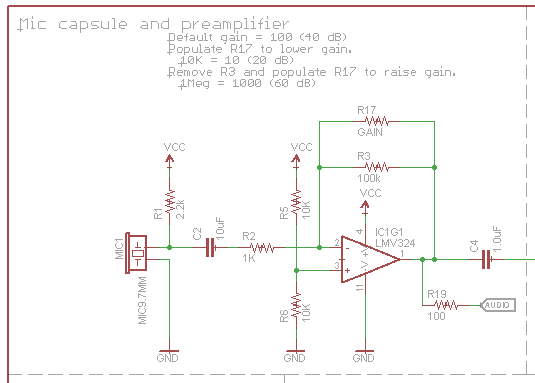
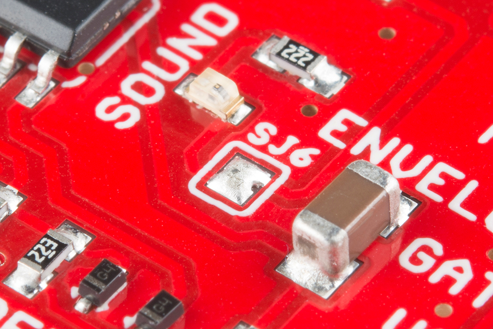
The gain is set by changing the feedback resistors in the preamp stage. The resistors are marked in the silkscreen
on the PCB.
Resistor Closeup
R3 is a surface mount part, with 100K Ohm populated by default. R17 is an unpopulated position for a through
hole resistor.
Lowering The gain