Speck MicPre 5.0 Manuale utente

MicPre 5.0
Microphone Preamp & Mix Node
Reference Manual


Speck Electronics products are warranted to the original owner to be free of
defects in material or workmanship.
This warranty does not apply to any product subject to accident, misuse, neglect
or failure to comply with normal maintenance procedures or if the serial number
has been defaced, altered, or removed; nor will Speck Electronics accept
responsibility for damages resulting from improper installation, alteration or
unauthorized parts or repairs. If the product is modified by the customer without
permission, the customer agrees to pay for parts and labor necessary to remove
the modification before repair. The cause of the defect is in the sole judgment of
Speck Electronics.
Should a defect develop within one year of purchase from Speck Electronics or
an authorized dealer, Speck Electronics will supply the part or parts necessary at
no charge. Labor is covered in this warranty for a period of one year. Outside
service, repairs or pickups are not covered under this warranty.
Any item returned for warranty repair should be sent, if possible, in the original
packing container, prepaid to Speck Electronics, 341 E. Alvarado Street,
Fallbrook, California, 92028. If in our opinion the packing container is
improper for return shipping, we reserve the right to supply a new container at a
minimal charge.
In the interest of improving Speck products; designs and specifications are
subject to change without notice. It should be mentioned that if a change is
necessary for any reason, we make every effort to document
that change and send an "update notice" to all customers at no charge.
Speck Electronics makes no warranty of any kind with regard to this material,
including, but not limited to, the implied warranties of merchantability and
fitness for a particular purpose. Speck Electronics shall not be liable for errors
contained herein or for incidental consequential damages in connection with the
furnishing, performance, or use of this material.
This document contains proprietary information which is protected by copyright.
All rights are reserved. No part of this document may be photocopied,
reproduced, or translated into another language without the prior written consent
of Speck Electronics.
The information contained in this document is subject to change without notice.
All trademarks are the property of their respective owners.
First Printing - September 2002
Speck Electronics
341 East Alvarado Street
Fallbrook, California 92028
USA
760-723-4281
www.speck.com
Warranty
Notice
Edition
ii

Contents
General .................................................................................
Standard Accessories ............................................................
Optional Accessories ............................................................
Operator Safety Summary .......................................................
Power source ........................................................................
Grounding the product .........................................................
Removing the cover .............................................................
General .................................................................................
Unpacking and inspection ....................................................
Environmental considerations ..............................................
Electrical grounding safety ..................................................
Mechanical installation ........................................................
Physical placement of adjacent equipment ..........................
Cleaning ...............................................................................
Repacking for shipment .......................................................
Basic connections to the MicPre 5.0 ........................................
The Input / Output connectors .............................................
Insert jacks ...........................................................................
Mixoutput jacks ...................................................................
Wiring the MP 5.0 to unbalanced inputs...............................
Mix Link Connector .............................................................
Connecting the MP 5.0 to the ASC Equalizer .............................
Interfacing two MP 5.0's..............................................................
Interfacing more than two MP 5.0's.............................................
Interfacing two MP 5.0's for M-S operation................................
General..................................................................................
Default control settings .........................................................
Signal flow diagram..............................................................
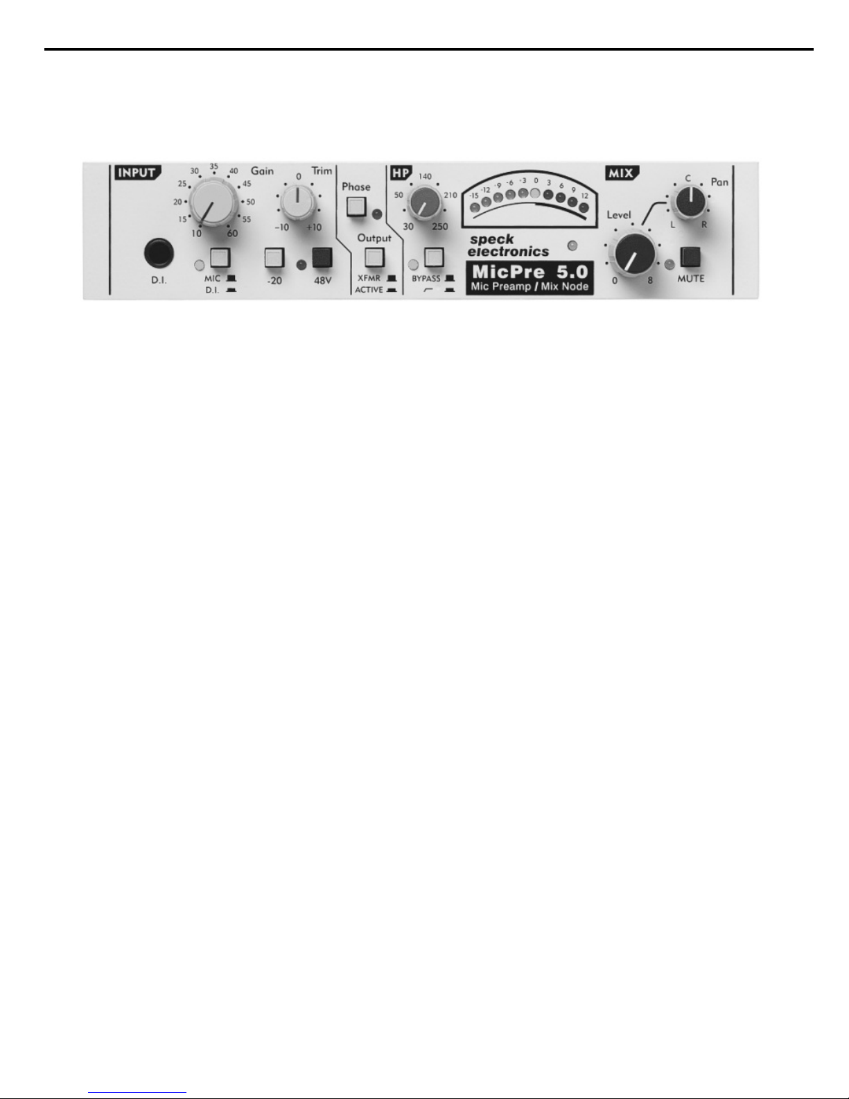
Front Panel Controls ................................................................
Gain switch............................................................................
Trim control ..........................................................................
Mic/DI select switch .............................................................
D.I. input jack .......................................................................
20dB Pad...............................................................................
48V Phantom switch .............................................................
Phase switch..........................................................................
Output select switch..............................................................
High Pass Filter control ........................................................
Filter bypass switch...............................................................
VU Meter ..............................................................................
Power indicator .....................................................................
Mix Level control .................................................................
Mix Pan control.....................................................................
Mix Mute switch ...................................................................
1
2
2
2
2
2
3
5
5
5
5
6
6
7
7
8
8
8
8
9
9
10
11
12
13
15
15
15
16
16
16
16
16
16
17
17
17
17
18
18
18
19
19
19
Chapter 1 Introduction
Chapter 2 Installation
Chapter 3 Operation
iii

Rear Panel .................................................................................
Microphone input ..................................................................
Preamp output ......................................................................
O.S.P. switch .........................................................................
Insert jacks ...........................................................................
Pre Out-B / Line In jacks .....................................................
Mix output jacks ...................................................................
Mix Link connector ..............................................................
Aux DC output .....................................................................
Power switch ........................................................................
AC power inlet......................................................................
Fuse .......................................................................................
Specifications..............................................................................
General .................................................................................
Start simple ..........................................................................
Audio Cable ................................................................................
Connectors ...........................................................................
AC Distribution and safety .........................................................
Proper AC grounding ...........................................................
Quality AC system ...............................................................
AC distribution .....................................................................
Clock noise and AC .............................................................
Safety earth connection ........................................................
Audio earth ...........................................................................
Proper audio grounding and shielding ........................................
EMI and RFI ...............................................................................
Sources of EMI ....................................................................
Reducing EMI ......................................................................
20
20
20
21
22
23
23
24
24
24
24
24
25
26
26
26
26
27
27
27
27
27
27
28
28
28
29
29
Chapter 4 Wiring and Other
iv

v

Introduction
Chapter 1 Introduction Section 1
Thank you for purchasing our MicPre 5.0 microphone
preamplifier. The MicPre 5.0 has operational features that are easy
to understand and you should be up and running in no time. If you
are unfamiliar with audio equipment or audio signal flow, it is
recommended that you read this manual. If you have any
questions regarding the MicPre 5.0 or any Speck product, do not
hesitate to contact Speck Electronics. Our phone number is
+760-723-4281.
The MicPre 5.0 is a complete single channel microphone preamp
that offers features and flexibility for use in recording, live sound
or any application that requires a high quality microphone preamp.
„In this manual the MicPre 5.0 will also be referred to
as the MP 5.0.
The signal path consists of a matched discrete transistor front-end,
premium IC's, and transformer output stage. With the push of a
button, the MP 5.0 can change from a "Transformer-Balanced"
output to a "Active-Balanced" output.
The MP 5.0 also includes a mix section that makes it perfect for
DAW's and remote recording. With an optional interface cable, the
mix section of the MP 5.0 can linked with additional MP 5.0’s to
form a fully integrated mix section.
The compact ½ rack format of the MP5.0 can easily be rack
mounted and combined with the Speck Model ASC equalizer to
create a highly functional outboard channel strip.
The MicPre 5.0 is available in 2 versions; The Model MP5.0-NA
designed to operate with 100 and 120 VAC power, and the Model
MP5.0-EU that is designed to operate with 220, 230 or 240 VAC
power.
General
MicPre 5.0 - Microphone Preamp and Mix Node

The MP5.0 is supplied with the following list of accessories:
Operations Manual
Power cord (NA version only)
(4) rubber bumpers - used for table top mounting or
stacking multiple units.
(2) 6-32 x ½” machine screws - supplied to mount the
MP 5.0 to an optional rack shelf.
The following is a list of optional accessories that are available
from the factory or your Speck dealer:
Mix link interface cables - to interface additional
MP 5.0’s.
2 unit cable - P/N MP50-Link2
4 unit cable - P/N MP50-Link4
6 unit cable - P/N MP50-Link6
8 unit cable - P/N MP50-Link8
M-S interface cable - a 12” cable used to connect two
MP5.0’s for use in a M-S micing configuration.
P/N MP50-MS
D.C. interface cable - Used to supply power to the
Model ASC equalizer.
P/N ASC-DCI
1U rack tray - may be used to rack mount two
MP 5.0’s or one MP 5.0 and one Model ASC equalizer.
The MP 5.0 is intended to operate from an AC power source that
does not apply more than 120 Volts RMS (Model MP5.0-NA) or
240 Volts RMS (Model MP5.0-EU) between the supply
conductors. Always make certain that power cord matches the
operating voltage shown on the rear panel above the power switch.
To avoid electrical shock, plug the power cord into a properly
wired receptacle. The ground pin of the power cord is internally
connected to the chassis. For safety reasons, do not lift the
ground on the power plug by using a ground lift adapter.
The MicPre 5.0 should never be exposed to rain or moisture.
Standard accessories
Optional accessories
Power Source
Grounding the product
Chapter 1 Introduction Section 2
Operator Saftey
Summary

To avoid personal injury, do not remove the top cover of the
MP 5.0 and never operate the MP 5.0 without the cover properly
installed.
The MP 5.0 with its internal power supply contains voltages that
can cause serious injury or death. Refer all repairs to a qualified
service technician, or directly to Speck Electronics.
Do not remove the cover
Chapter 1 Introduction Section 3

Chapter 1 Introduction Section 4
~ This page left intentionally blank ~
Indice


