SpiderCloud SCRN-330 Manuale
SpiderCloud® Radio Node - SCRN-330
Hardware Installation Guide
Part number: DOC-SCRN-330-HW-01, Rev. 1
Published: April 2018
DRAFT

2
FCC Statements
Caution: Any changes or modification cautions to this device not explicitly approved by manufacturer could void your
authority to operate this equipment.
This equipment complies with FCC radiation exposure limits set forth for an uncontrolled environment. This equipment
should be installed and operated with minimum 25 cm between the radiator and your body. This transmitter must not
be collocated or operating in conjunction with any other antenna or transmitter unless authorized to do so by the FCC.
This device can be expected to comply with part 15 of the FCC Rules provided it is assembled in exact accordance
with the instructions provided with this kit. Operation is subject to the following conditions: (1) This device may not
cause harmful interference, and (2) this device must accept any interference received including interference that may
cause undesired operation.
Legal Notice
Customer agrees that the Software, including the specific design and structure of individual programs, and
the Documentation are protected by United States and foreign copyright and trade secret laws. Customer
agrees not to reproduce, disclose, alter, provide or otherwise make available such trade secrets or
copyrighted material in any form to any third party without the prior written consent of SpiderCloud
Wireless. Customer agrees to implement reasonable security measures to protect such trade secrets and
copyrighted material at least to the extent that Customer protects its own information of a similar nature.
The information contained herein is subject to change without notice. Although all information is believed
to be accurate at the date of publication, SpiderCloud assumes no responsibility for inaccuracies contained
herein.
Copyright © 2018 SpiderCloud Wireless, Inc. SpiderCloud Wireless is a registered trademark and
SmartCloud a trademark of SpiderCloud Wireless, Inc. All rights reserved.
SpiderCloud Wireless
475 Sycamore Drive
Milpitas, CA 95035, USA
http://www.spidercloud.com
Tel: +1 408 235-2900
Email: [email protected]
Revision History
Revision Date Summary of Changes
1 4/9/2018 Initial draft document release
SpiderCloud Wireless, Inc. Proprietary and Confidential
DRAFT

SpiderCloud Radio Node - SCRN-330 Hardware Installation Guide
3
Table of Contents
About this Manual . . . . . . . . . . . . . . . . . . . . . . . . . . . . . . . . . . . . . . . . . . . . . . . . . . . . . . . . . . . 5
Product Overview . . . . . . . . . . . . . . . . . . . . . . . . . . . . . . . . . . . . . . . . . . . . . . . . . . . . . . . . . . . 5
Radio Node Models . . . . . . . . . . . . . . . . . . . . . . . . . . . . . . . . . . . . . . . . . . . . . . . . . . . . . . . . . . 6
Radio Node System Isometric Top View and Bottom View. . . . . . . . . . . . . . . . . . . . . . . . . . 7
Antennas. . . . . . . . . . . . . . . . . . . . . . . . . . . . . . . . . . . . . . . . . . . . . . . . . . . . . . . . . . . . . . . . . . . 8
Ports . . . . . . . . . . . . . . . . . . . . . . . . . . . . . . . . . . . . . . . . . . . . . . . . . . . . . . . . . . . . . . . . . . . . . . 8
The Top-Panel LED . . . . . . . . . . . . . . . . . . . . . . . . . . . . . . . . . . . . . . . . . . . . . . . . . . . . . . . . . . 9
Input Power . . . . . . . . . . . . . . . . . . . . . . . . . . . . . . . . . . . . . . . . . . . . . . . . . . . . . . . . . . . . . . . . 9
System Specifications. . . . . . . . . . . . . . . . . . . . . . . . . . . . . . . . . . . . . . . . . . . . . . . . . . . . . . . . 11
SCRN-330 Bracket Specifications. . . . . . . . . . . . . . . . . . . . . . . . . . . . . . . . . . . . . . . . . . . . . 12
Compliance. . . . . . . . . . . . . . . . . . . . . . . . . . . . . . . . . . . . . . . . . . . . . . . . . . . . . . . . . . . . . . . . . 13
Radio Specifications . . . . . . . . . . . . . . . . . . . . . . . . . . . . . . . . . . . . . . . . . . . . . . . . . . . . . . . . . 13
Select the Radio Node Location. . . . . . . . . . . . . . . . . . . . . . . . . . . . . . . . . . . . . . . . . . . . . . . . 13
Installation and Mount Bracket Assembly. . . . . . . . . . . . . . . . . . . . . . . . . . . . . . . . . . . . . . . . 14
Bracket Mounting and Cabling Guidelines . . . . . . . . . . . . . . . . . . . . . . . . . . . . . . . . . . . . . . 14
Typical Radio Node Mounting Options . . . . . . . . . . . . . . . . . . . . . . . . . . . . . . . . . . . . . . . . . 15
Installing the Radio Node . . . . . . . . . . . . . . . . . . . . . . . . . . . . . . . . . . . . . . . . . . . . . . . . . . . 15
Installing the Radio Node (Method 1) . . . . . . . . . . . . . . . . . . . . . . . . . . . . . . . . . . . . . . . . . . 16
Installing the Radio Node (Method 2) . . . . . . . . . . . . . . . . . . . . . . . . . . . . . . . . . . . . . . . . . . 17
Completing the Installation . . . . . . . . . . . . . . . . . . . . . . . . . . . . . . . . . . . . . . . . . . . . . . . . . . 19
Detaching the Radio Node from the Mount Bracket . . . . . . . . . . . . . . . . . . . . . . . . . . . . . . . 19
Boot Sequence and Services Node Communication . . . . . . . . . . . . . . . . . . . . . . . . . . . . . . . 20
Radio Node LED Boot Sequence . . . . . . . . . . . . . . . . . . . . . . . . . . . . . . . . . . . . . . . . . . . . . . . 21
Radio Node LED Management . . . . . . . . . . . . . . . . . . . . . . . . . . . . . . . . . . . . . . . . . . . . . . . . . 22
The SpiderCloud Documentation Set . . . . . . . . . . . . . . . . . . . . . . . . . . . . . . . . . . . . . . . . . . . 23
Appendix A LTE Antenna Patterns . . . . . . . . . . . . . . . . . . . . . . . . . . . . . . . . . . . . . . . . . . . . . 25
SpiderCloud Wireless, Inc. Proprietary and Confidential
DRAFT

Contents
4
SpiderCloud Wireless, Inc. Proprietary and Confidential
DRAFT

5
SpiderCloud Radio Node - SCRN-330 Hardware Installation Guide
About this Manual
This guide provides the system specifications of the SpiderCloud Wireless® Radio Node 330 (SCRN-330).
It includes detailed hardware installation instructions, the boot sequence, and expected LED behavior both
during the boot-up and under operating conditions. An appendix shows the radio node antenna patterns.
The primary audience for this guide includes network planners, system administrators and installation
personnel. It assumes you have knowledge about networking principles, networking configuration, site
preparation, powering, and experience in hardware installation and maintenance.
Product Overview
The SCRN-330 is a Time Division Duplexing (TDD) radio node that connects to a services node. It uses
GPS to achieve phase synchronization with macro networks. Each radio node support 128 connected
users and up to 8 bearers per UE. It supports peak transmit power of 2x250mW and uses Powered over
Ethernet plus (PoE+). This radio node supports CBRS technology, which enables services such as private
LTE networks and neutral host systems.
SpiderCloud’s scalable small cell system, called an Enterprise Radio Access Network (E-RAN), hides the
complexity of radio management and mobility and provides operators with a single touch-point to
aggregate and manage a large network of LTE small cells. The SCRN-330 leverages Carrier Aggregation
(CA) and Self-Organizing Networks (SON) capabilities.
The SCRN-330 is easy to install and connects to the existing enterprise LAN using standard Ethernet
cabling or to a dedicated LAN infrastructure deployed for use by the operator. SCRN-330 radio node are
managed by the SpiderCloud SCSN-9000 services node installed in the enterprise or in a centralized
location such as a data center.
The SCRN-330 has no fans and is convection cooled. Antennas are built-in with an orderable option for
SMA connectors for use with external antennas.
The SCRN-330 utilizes on-chip Trusted Platform Module (TPM) functions to implement secure boot, and
establish certificate-based IPsec tunnel to SpiderCloud services node for all traffic. There is no
management or console port on the radio node. The radio node can be physically locked to prevent theft.
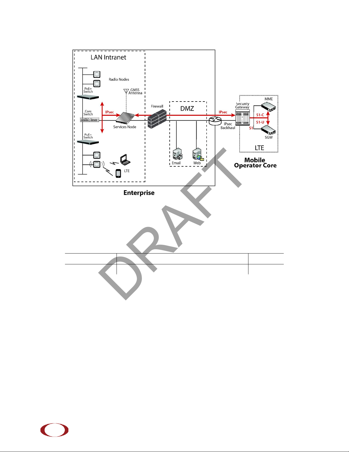
Figure 1 on page 6 shows the logical architecture of the SCRN-330 in the network:
SpiderCloud Wireless, Inc. Proprietary and Confidential
DRAFT
SpiderCloud Radio Node - SCRN-330 Hardware Installation Guide
6
Figure 1 Radio Node Relationship to Enterprise and Mobile Operator Core Networks
Radio Node Models
Table 1 displays the orderable configuration of the SCRN-330 radio node:
Table 1: SCRN-330 Radio Node Configurations
Radio Node Model Description Antenna Type
SCRN-330-4148 LTE bands 41 and 48 Internal
SpiderCloud Wireless, Inc. Proprietary and Confidential
DRAFT
SpiderCloud Radio Node - SCRN-330 Hardware Installation Guide
7
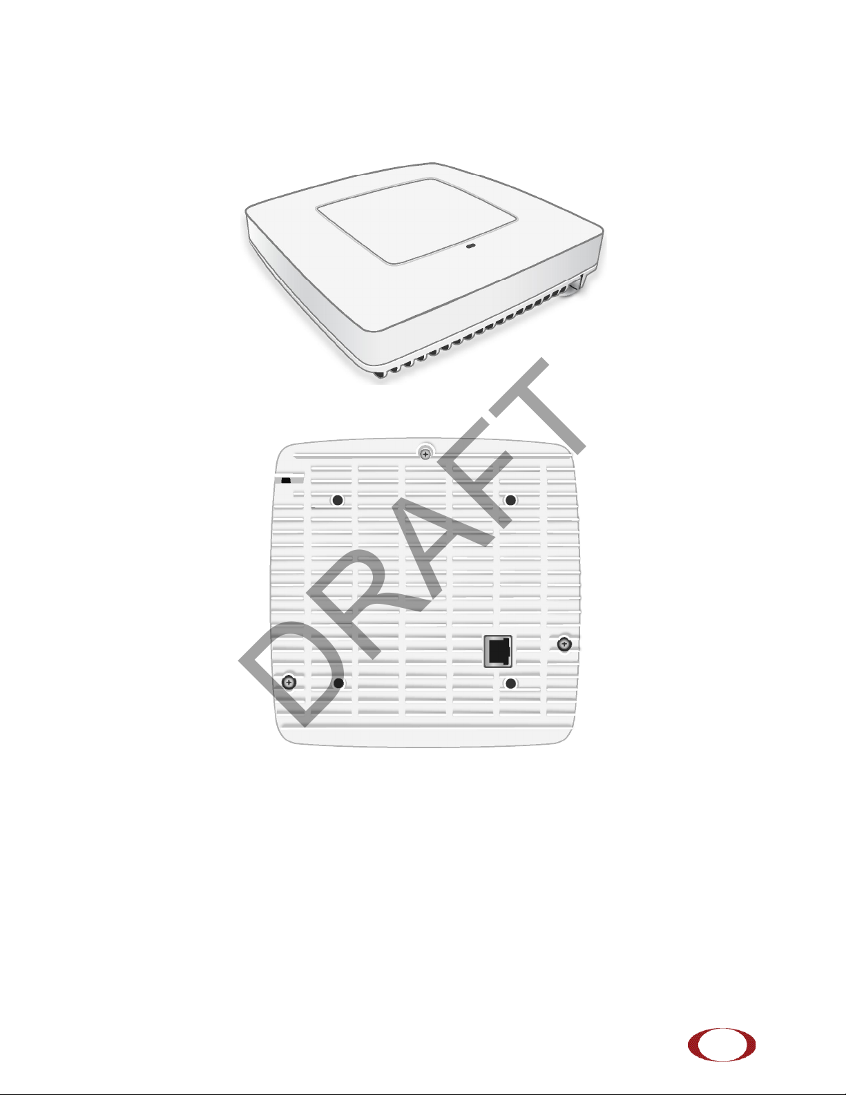
Radio Node System Isometric Top View and Bottom View
The following drawings display an isometric top and bottom views of the radio node:
Figure 2 Radio Node Top View
Figure 3 Radio Node Bottom View
SpiderCloud Wireless, Inc. Proprietary and Confidential
DRAFT
SpiderCloud Radio Node - SCRN-330 Hardware Installation Guide
8
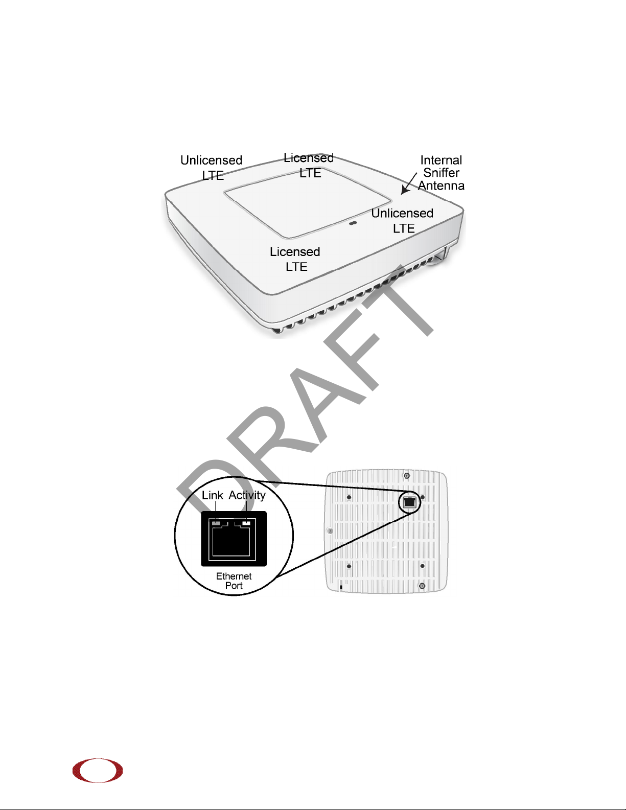
Antennas
The radio node includes four internal Tx/Rx antennas with a peak gain of 5dBi and operates in 2x2 mode
with MIMO and one internal network listen antenna:
Figure 4 shows the location of the licenced and unlicensed LTE antennas:
Figure 4 Antenna Band Locations
Ports
The radio node has one 1 Gigabit Ethernet port that supports a Category 5e (Cat 5e) or better twisted-pair
cable with an RJ-45 connector. Figure 5 shows the Ethernet port. There are two LEDs on the connector:
•Link: Steady green state indicates a normal Layer 2 link connection has been established.
•Activity: Yellow blinking indicates data activity.
Figure 5 Ethernet Port
SpiderCloud Wireless, Inc. Proprietary and Confidential
DRAFT
SpiderCloud Radio Node - SCRN-330 Hardware Installation Guide
9
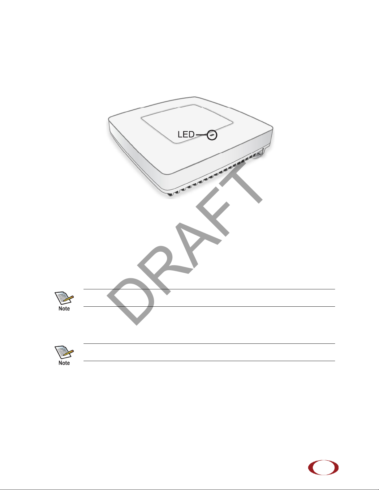
The Top-Panel LED
The radio node has one top-panel tricolor (RGB) LED to indicate power and status. This is the only LED
visible under normal operating conditions. When the radio node initially boots the LED cycles through a
number of colors and flashing behaviors until it is fully operational. Status indications: boot, normal,
disabled, fault, emergency call, radio node tracking.
Figure 6 Radio Node Tricolor LED
Input Power
The radio node receives its power from a standard Power Over Ethernet (PoE+) switch (typical) or injector.
The radio node is fully compliant with the IEEE 802.3at PoE+ specification.
Per IEEE 802.3at, use standard Cat 5e or better twisted-pair cable with a maximum length restriction of
100 meters (328 feet) for PoE+. This restriction minimizes power loss between the PoE+ power source
and the radio node.
When connecting the radio node to a PoE+ switch, ensure that the switch port is statically configured to
deliver minimum 25W of power.
Power is distributed over two pairs of the four available pairs in Cat 5e or better cables. The
radio node can accept power on either used or un-used pairs.
Some PoE switches may be factory configured to deliver lower power per port. If this is the
case change the configuration during installation.
SpiderCloud Wireless, Inc. Proprietary and Confidential
DRAFT
SpiderCloud Radio Node - SCRN-330 Hardware Installation Guide
10
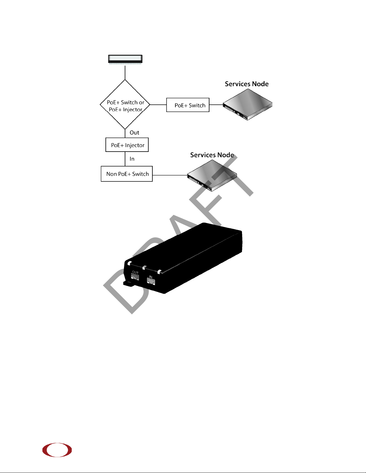
Figure 7 shows the valid radio node cabling/powering options:
Figure 7 Valid Radio Node Cabling/Powering Options
The illustration below shows a generic single-port PoE+ injector. Use this injector only when a PoE+
Ethernet switch is not available.
Figure 8 Typical PoE+ Injector
To connect the PoE+ injector to a radio node
Step 1 Attach the injector power cord to a power source.
Step 2 Connect an unpowered Ethernet cable from a switch to the IN port on the injector.
Step 3 Connect an Ethernet cable from the injector’s OUT port to the radio node. The injector will
now inject power onto a pair of wire pairs in the cable. The radio node will expect a nominal
48V DC input (57V max) from a typical PoE+ injector.
SpiderCloud Wireless, Inc. Proprietary and Confidential
DRAFT
Indice
Altri manuali SpiderCloud Sistema microfonico


Manuali Sistema microfonico popolari di altre marche


Sennheiser
Sennheiser Evolution Wireless Digital EW-DX EM 2 Manuale utente

Alpha Technologies
Alpha Technologies RBMS Manuale utente

SWIT Electronics Co.,LTD.
SWIT Electronics Co.,LTD. CW-S150 Manuale utente

Shure
Shure UA844 Manuale utente

Panasonic
Panasonic SHFX70 - DVD HOME THEATER WIRELESS SYSTEM Manuale utente

Pyle
Pyle PDWM5000 Manuale utente