SpraMigo TCB100 Manuale utente
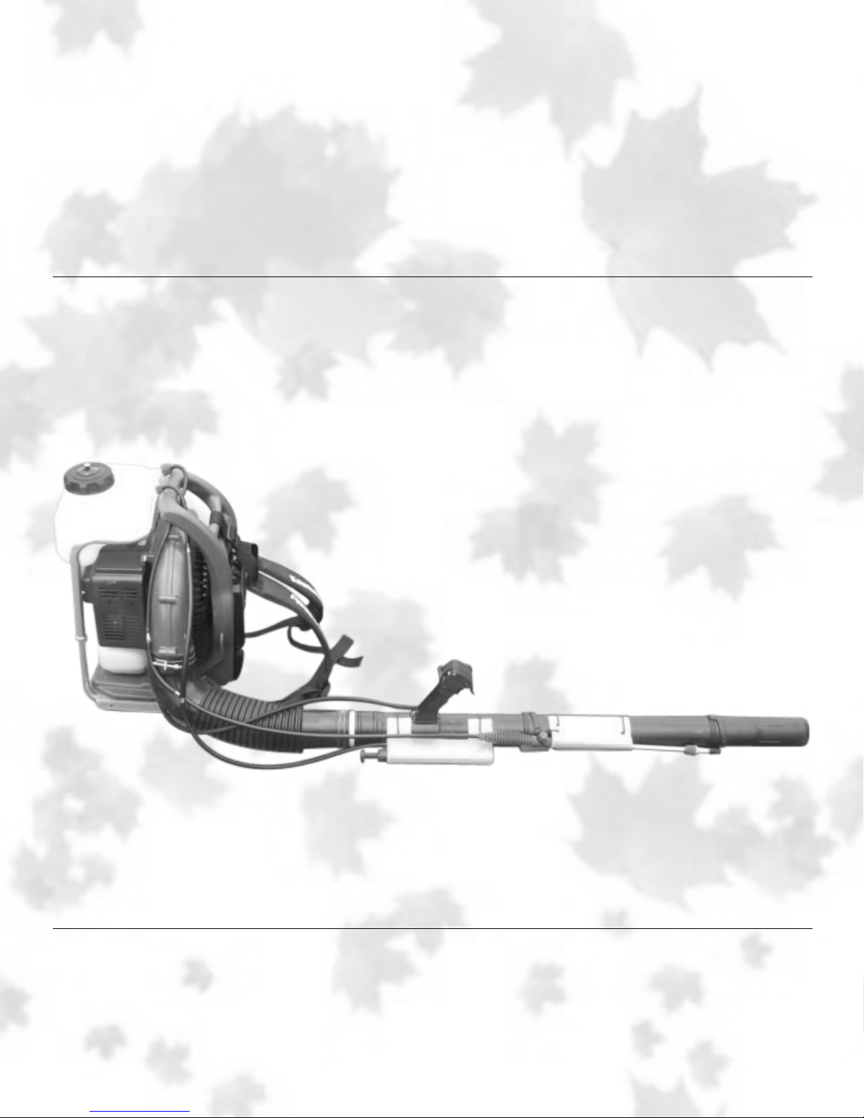
SpraMigo TCB100
www.spramigo.com
SpraMigo can be mounted on blowers from these manufacturers:
ECHO STIHL REDMAX
MARUYAMA TANAKA KAWASAKI
see page 1 for specific models
SpraMigo
1-877-921-1194
P.O. Box 44128
Charlotte, NC 28213
Curb appeal is most
important


TABLE OF CONTENTS
SAFETY WARNINGS....................................................................
BOX CONTENTS..........................................................................
HARDWARE NEEDED..................................................................
OPERATING SPRAYER................................................................
MODEL SPECIFIC ASSEMBLY
STIHL BR340, BR380, BR420......................................................
STIHL BR500, BR 550, BR600.....................................................
RED MAX EBZ 5100, EBZ 7001, EB7001, EBZ 7100, EBZ 7150
-Tanaka TBL 7800, TBL 7800R
KAWASAKI KRB 750A, KRB 750B, KRB 650B............................
-Maruyama BL 5100, BL 8100, BL 8101, BL 8200
ECHO PB413T, PB500H, PB500T, PB620H, PB620ST................
SPRAYER ASSEMBLY .................................................................
PART AND ASSEMBLY DETAIL....................................................
MAINTENANCE............................................................................
TROUBLESHOOTING..................................................................
WARRANTY INFORMATION........................................................
1
2
3
4
5
6-7
8-9
10-11
12-13
14-15
16
17
18
19
20

! WARNING !
BEFORE YOU ASSEMBLE AND USE YOUR SPRAYER PLEASE READ THE
FOLLOWING SAFETY INFORMATION
• This sprayer operates with liquid under pressure.
• Failure to observe cautions and follow instructions for use and
maintenance can cause tank, hoses, or other parts to become
corroded, weakened and burst. This can result in serious injury or
property damage.
• Donotuseammablesinthissprayer.
• Do not spray near heat source.
• Always water test unit before use.
• Always wear protective clothing, protective eye wear and gloves.
• Release pressure in sprayer before servicing.
• This product is designed to spray chemicals that may be harmful and
could cause serious personal injury if inhaled or brought into contact
with the user.
• Always release pressure from tank after use
• Do not store liquid in tank.
• Failure to set sprayer aluminum frame in correct frame setting for
yourparticularblowercanweakenandbursttankfromblowermufer
exhaust heat which could result in injury or property damage.
Important Note: When operating blower/sprayer combination, always
blow area off rst then spray chemicals on weeds so as not to blow
chemicals on to grass, plants, other materials, etc.
2
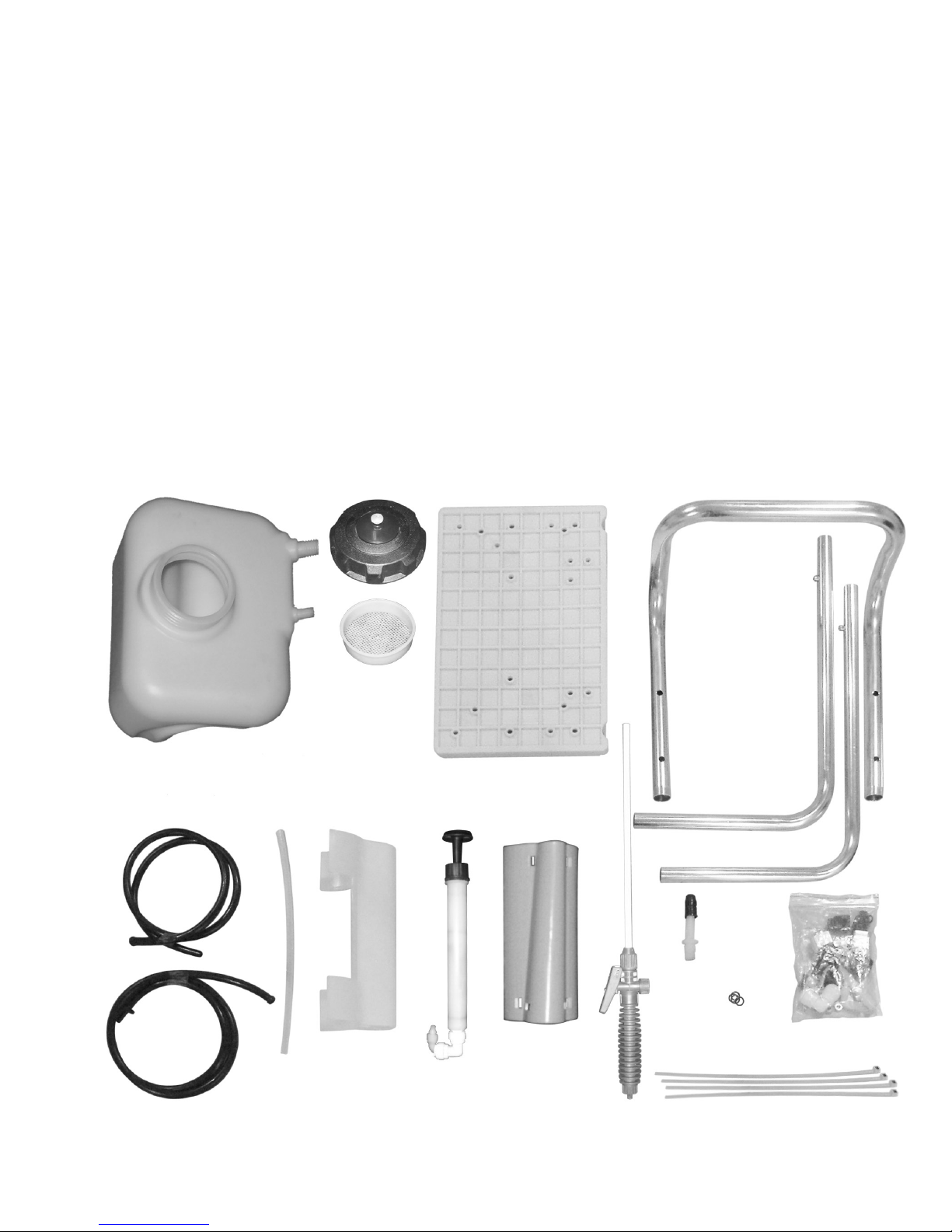
BOX CONTENTS
a. TANK
b. TANK CAP
c. TANK FILTER
d. BASE
e. TANK MOUNTING FRAME
(3pc)
f . PUMP HOSE
g. FLOW HOSE
h. SIPHON TUBE
i . PUMP HOUSING
j . PUMP
k. WAND HOUSING
l . WAND ASSEMBLY
m. ADJUSTABLE NOZZLE
n. HARDWARE BAG
o. PUMP & WAND HOLDER
TIES - 14” #4
p. PUMP “O” RING
a.
f.
g. o.
h. i. j. k. l.
m.
p.
o.
n.
b.
c.
d.
e.
3

Hardware Needed***
Screws Flat Washers
(4) #10-32x1” (8) #10-32
(6) #10-32x1 1/4”
(2) #10-32x1 1/2”
(2) #10-32x1 3/4”
(4) #10-32x2”
Lock Washers Tee Nuts
(8) #10-32 (4) #10-32x5/16”
1” Screw
1 1/4” Screw
1 1/2” Screw
1 3/4” Screw
2” Screw
***Not all hardware will be used.
Tools Needed
Drill
5/64” Drill Bit
1/4” Drill Bit
2 C-clamps
Phillips Head Screwdriver
Threadlockeruid(useonallscrews)
4

Operating Your Sprayer
1. Remove lid from tank.
2. Prepare spray solution following instructions provided with chemicals.
3.Whensprayerislledtocorrectmarkontank,closetanklid.
4. Put backpack blower/sprayer on your back and pressurize sprayer
when ready for use.
Important Note: When operating blower/sprayer combination, always
blow area off rst then spray chemicals on weeds so as not to blow
chemicals on to grass, plants, other materials, etc.
1.Pullwandoutofwandholderandsqueezetheowcontrollever.
2.Tospraycontinuously,squeezetheowcontrolleverandslidethe
locking mechanism forward.
3.Foranemist,turntheadaptablenozzleclockwise.Turnitcounter
clockwise for a coarse stream.
4. To depressurize the tank loosen tank lid slightly.
5

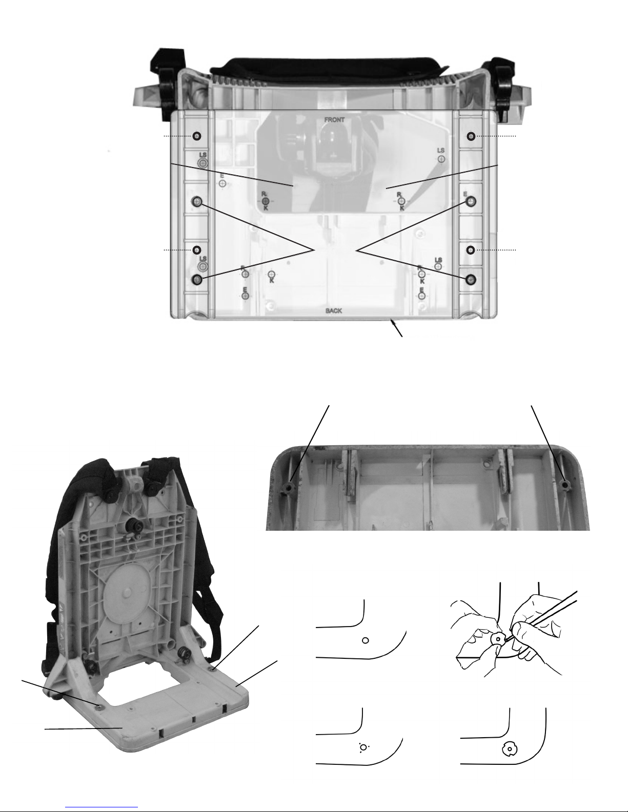
FOR BLOWER MODELS: STIHL BR340, 380 & 420
(REQUIRES 19.5” ALUMINUM FRAME SETTING)
IMPORTANT: USE LETTERS SS MARKED ON NEW BASE FOR INSTALLATION TO BLOWER
FRAME ON ALL MODELS LISTED ABOVE.
Mounting New Base to Blower Frame
1.Removegastankfromblower(removegasfromtankrst).
2. Remove blower body from blower frame.
3. Remove blower handle located on top of blower.
4. Turn blower frame upside down with back of blower frame closest to you. See illustration A-1.
5. Find two existing screw holes located on back corners of blower frame. See Back Corner Detail illustration
A-1v.
6. Place new base on bottom of blower frame. Align SS holes marked at rear of new base with existing holes
on blower frame using a #10-32X1” screw. Screw 1” screw through new base marked SS on blower frame.
Repeat for opposite side of base, using holes marked SS.
7. Once the new base is secured to the blower frame, drill (2) 1/4” holes on the front of the blower frame. Use
SS on the base for a guide.
8. Install (2) tee nuts in 1/4” holes on blower frame.
9. Installing Tee Nuts:
See illustration Tee Nut Installation
A. Place tee nut in 1/4” hole and press until the three prongs contact the frame.
B. With a pen, mark the spots where the three prongs touch the frame.
C. Remove tee nut. Using a 5/64” bit, drill a hole centered within the three pen marks.
D. Press tee nut into place and repeat with remaining tee nut.
10. Remove base. Reinstall gas tank.
11. With gas tank in place, reinstall base on blower frame using (2) #10-32X1” for base back and (2) #10-32X1
3/4” screws for base front.
12. Securing New Base to Blower Frame:
Use holes marked SS. To avoid frame damage, DO NOT OVER TIGHTEN SCREWS.
Hardware needed:
(2) #10-32X1” Screws (back of frame)
(2) #10-32X1 3/4” Screws (front of frame)
(2) #10-32X5/16” Tee Nuts
13. Reattach blower body to frame.
14. Assembling Aluminum Frame:
A. Slide L-shaped piece into aluminum frame piece.
B. Snap pin into correct position for your blower model and tighten screw cap by hand. Repeat
for other side.
15. Mounting Aluminum Frame to New Base
A. Place aluminum frame legs in two slots of new base with ends of legs toward front of blower
frame.
B. Locate letters FM marked on each side of the base.
C. Install #10-32x1 1/4” screws to support aluminum frame.
Hardware Needed:
(4) #10-32x1 1/4” Screws
(4) #10-32 Flat Washers
(4) #10-32 Lock Washers
16. Mounting Spray Tank to Aluminum Frame
A. Unscrew caps on each side of installed frame.
B. Push adjustable snap pins in and remove top aluminum piece.
C. Pull on each side of frame to allow space for tank to snap into place.
D. Reconnect aluminum pieces.
6
12
3 4
TEE NUT INSTALLATION
(STEP 9)
FRAME
A-1
1
2
4
3
1
4BACK CORNER DETAIL
ALIGN WITH BACK
1
23
4
FM
FM
FM
FM
SS
SS
SS
SS
CENTER FRAME
BRACKET EQUAL WITH
BOTH SIDES
420 STIHL
7

FOR BLOWER MODELS: STIHL BR500, 550 & 600
(REQUIRES 19.5” ALUMINUM FRAME SETTING)
IMPORTANT: USE LETTERS LS MARKED ON NEW BASE FOR INSTALLATION TO BLOWER
FRAME ON ALL MODELS LISTED ABOVE.
Mounting New Base to Blower Frame
1.Removegastankfromblower(removegasfromtankrst).
2. Remove blower body away blower frame.
3. Set base down and place blower frame on top of base, using marked lines on base for proper alignment.
See illustration A-2. Using C-clamps or some other method, secure frame to base. Turn frame and base
upside down while keeping proper alignment. See illustration A-2.
4. Drill (4) 1/4” holes using LS marks as guides. Unclamp frame and base.
5. Install (4) tee nuts in 1/4” holes on blower frame.
6. Installing Tee Nuts:
See illustration Tee Nut Installation
A. Place tee nut in 1/4” hole and press until the three prongs contact the frame.
B. With a pen, mark the spots where the three prongs touch the frame.
C. Remove tee nut. Using a 5/64” bit, drill a hole centered within the three pen marks.
D. Press tee nut into place and repeat with remaining tee nuts.
7. Reinstall gas tank and blower body to blower frame.
8. Securing New Base to Blower Frame:
Use holes marked LS. To avoid frame damage, DO NOT OVER TIGHTEN SCREWS.
Hardware needed:
(1) #10-32x1 1/4” Screw (Back Right) (2) #10-32 Flat Washers
(1) #10-32x1” Screw (Back Left - no washers) (2) #10-32 Lock Washers
(1) #10-32x1 1/2” Screw (Left Front of Frame - no washers) (4) #10-32x5/16” Tee Nuts
(1) #10-32x1 1/2” Screw (Front Right of Frame)
9. Assembling Aluminum Frame:
A. Slide L-shaped piece into aluminum frame piece.
B. Snap pin into correct position for your blower model and tighten screw cap by hand. Repeat
for other side.
10. Mounting Aluminum Frame to New Base
A. Place aluminum frame legs in two slots of new base with ends of legs toward front of blower
frame.
B. Locate letters FM marked on each side of the base.
C. Install #10-32x1 1/4” screws to support aluminum frame.
Hardware Needed:
(4) #10-32x1 1/4” Screws
(4) #10-32 Flat Washers
(4) #10-32 Lock Washers
11. Mounting Spray Tank to Aluminum Frame
A. Unscrew caps on each side of installed frame.
B. Push adjustable snap pins in and remove top aluminum piece.
C. Pull on each side of frame to allow space for tank to snap into place.
D. Reconnect aluminum pieces.
8
Indice


