
Stage Accompany EFFICIENCY SERIES ES 20 Manuale utente
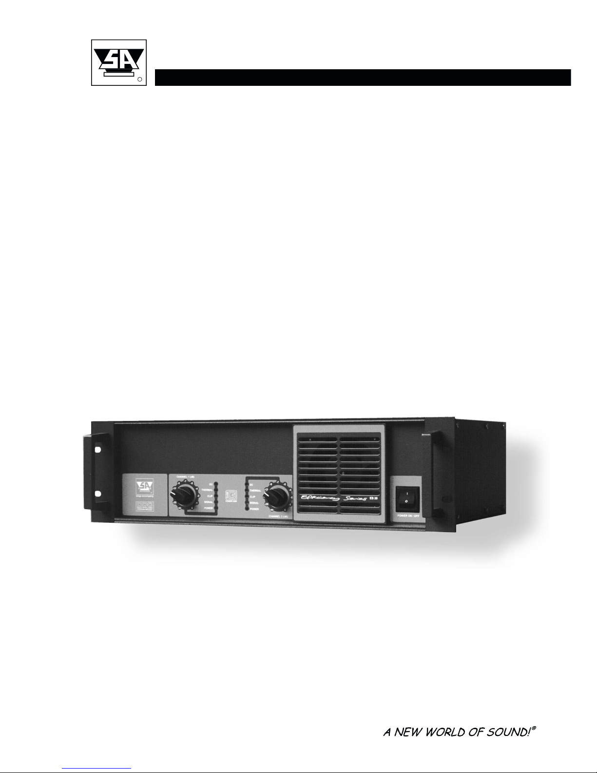
EFFICIENCY SERIES ES 20
High Efficiency Power Amplifier
User Manual
stage accompany
R
ES 20 USER MANUAL

Published by:
New Stage Accompany B.V.
Training & Documentation
Anodeweg 4
1627 LJ Hoorn, The Netherlands
Copyright © 1998 by New Stage Accompany B.V.
All rights reserved. No part of this manual may be reproduced or transmitted in any form or by
any means, electronically or mechanical, without written permission from New Stage Accom-
pany B.V. , except for the inclusion of brief quotations in a review.
First printing, May 1998
Printed in The Netherlands
This manual is intended to provide information about the Stage Accompany ES 20. Every effort
has been made to make this manual complete and as accurate as possible. However no
warranty of suitability, purpose, or fitness is implied. The information is provided on an “as-is”
basis. New Stage Accompany B.V. shall have neither liability nor responsibility to any person
or entity with respect to any loss or damages in connection with or arising from the information
contained in this manual.
New Stage Accompany B.V. reserves the right to alter specifications without prior notice.
stage accompany
R
ES 20 USER MANUAL

stage accompany
R
ES 20 USER MANUAL
Table of Contents
Quick Introduction to the ES 20
Introduction
Connections
Operation
Recommendations
Technical Specifications
Warranty
Overview

Table Of Contents
1 Quick Introduction to the ES 20 ................................. 1-1
2 Introduction ................................................. 2-1
3 Connection of the ES 20 ....................................... 3-1
3.1 Mains Power Connection ................................... 3-1
3.2 Audio Connections ........................................ 3-4
3.3 Loudspeaker Connections .................................. 3-5
4 Operation ................................................... 4-1
4.1 Input Attenuators ......................................... 4-1
4.2 Bridge Mode Switch ....................................... 4-1
4.3 Ground Lift Switch ........................................ 4-2
4.4 Indicators ............................................... 4-2
5 Recommendations for Optimum Use............................. 5-1
6 Technical Specifications....................................... 6-1
7 Warranty .................................................... 7-1
8 Overview.................................................... 8-1
TABLE OF CONTENTS
stage accompany
R
ES 20 USER MANUAL

1 Quick Introduction to the ES 20
Thank you for choosing a Stage Accompany Power Amplifier. Making this choice has guaran-
teed you many years of troublefree amplification.
If you have to start using the ES 20 straight away and do not have time to read the complete
manual, make sure that you at least read the following:
•Ensure that you have a reliable, well earthed power source. The required current for
the ES 20 can be found in the table in paragraph 3.1.
•Connect the ES 20 to your signal sources via the <INPUT> connectors. Connect this
amplifier to other units via the <LINK> outputs using short signal leads. Connect your
single signal source to the channel 1 input if you use the ES 20 in bridge mode.
•Never make connections to the amplifier or to any preceding equipment with the ampli-
fier switched on!
Important
When combining ES 20s with a Stage Accompany Blue Box system,you must take into account
thatthelow-frequency loudspeakeroftheBlueBoxhasanexcursionoppositetothatofanormal
speaker-amplifier combination. The Blue Boxes in combination with the ES 20s have to be
switched to inverted phase, or cross cables for ES 20s or Blue Boxes have to be used!
•Switch the ES 20 on using the <POWER ON/OFF> switch.
If you want to use the ES 20 in bridge mode, set the <MODE> switch at the back of the amplifier
in the <BRIDGE MODE> position. Connect the speaker system to the <BRIDGE MODE
OUTPUT>.
•Select the desired input sensitivity by means of the <INPUT ATTENUATORS>. In
bridge mode, always set the input attenuators in the same position.
•Any earth hum that may be present may be solved with the <GROUND LIFT> switch.
The ES 20 is now ready for use.
QUICK INTRODUCTION
stage accompany
R
ES 20 USER MANUAL
1-1

2 Introduction
The Stage Accompany ES 20 is a dual channel, high efficiency power amplifier and comprises
the following components:
•Balanced input stages.
•Two high efficient amplifiers which deliver each 500 Wrms into 8Ω, 770 Wrms into 4 Ω
and 960 Wrms into 2Ωor 610 W peak into 8 Ω, 1000 W peak into 4 Ω, and 1400 W
peak into 2 Ω
.
•Advanced protection circuits.
The audio inputs and link outputs are connected internally without electronics. This is done to
prevent any loss of sound quality. With an input impedance of 22 kΩ, it is possible to connect
a maximum of 30 ES 20s to a 600 Ωsource like the SA 1310 graphic equaliser. If more than
30 units need to be connected to a single source, a separate signal driver must be used.
The ES 20 is protected against the connection of speaker impedances less than 2 Ωor even
short circuiting of the output. In these cases the output current is limited but the amplifier keeps
working.
The ES 20 has a number of features, including:
•High efficiency class G operation.
•Variable speed DC fan.
•DDC (Dynamic Damping Control).
•EFN circuit (Extended Function Network)
•Soft start to reduce power on inrush current.
•Temperature, DC, HF and short circuit protection.
Class G operation
The power supply of the ES 20 amplifier produces 2 different supply levels. Each channel
actually consists of two power amplifiers. One produces the output signal, the other one selects
the power supply voltage. This way, the ES 20 uses the low level supply at low output power
and the high level supply at high output power which reduces internal dissipation significantly.
INTRODUCTION
stage accompany
R
ES 20 USER MANUAL
2-1

DC Fan
The built in DC fan has a continuous variable speed. Its control circuit monitors the temperature
oftheoutputdevicesandthetemperatureofthepowersupply.Thespeedofthefaniscalculated
out of this information. This system ensures that the fan always runs at optimum speed and
thus produces less noise.
DDC
DDC (Dynamic Damping Control) is a special way of measuring the cone movement of a
loudspeaker. The voltage induced in the voice coil is sensed and fed back to the amplifier’s
feedbackcircuit.Hence,a virtuallyinfinitedampingisachieved,whichresultsinanexceptionally
tight sound reproduction.
EFN
Through the internal EFN circuit, with plug-in modules, extra functions can be added to the
amplifier, like cross-over, high- low- or band-pass filtering, equalisation and loudspeaker
protection. Special protection boards are available for all Stage Accompany loudspeaker
systems. The installation of an EFN module needs to be done by an authorized Stage
Accompany service center.
Soft Start
The soft start circuit is active when the ES 20 is turned on. The mains inrush current, which
normally is in excess of 100 A is limited to a safe value. However, take care not to switch on
too many ES 20 amplifiers at the same time, or you risk that the main fuses of your distribution
may trip.
Temperature, DC, HF and Short Circuit Protection
The amplifier and the loudspeakers are protected against all possible damages.
INTRODUCTION
stage accompany
R
ES 20 USER MANUAL
2-2
3 Connections
Only three connections need to be made: mains power, audio input signals, and loudspeaker
leads. Do not make any connections to the amplifier or to any preceding equipment with the
amplifier switched on!
3.1 Mains Power Connection
The ES 20 is internally selectable for 110-120/220-240V 50/60Hz mains voltage. The exact
voltages are stated at the rear of the amplifier. Switching between mains voltages has to be
done by an authorised Stage Accompany service centre. Connecting to the wrong voltage is
dangerous and may damage the amplifier. Always ensure that you use a correctly grounded
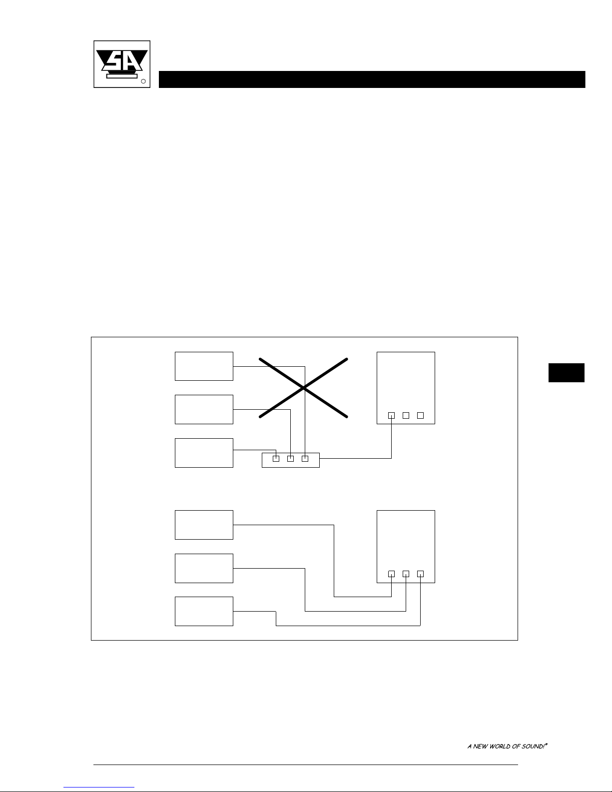
power supply. If more than one ES 20 is to be used, it is advisable to connect each one
separately to the nearest mains supply in stead of connecting several ES 20s using an adapter
block (see figure 3-1).
Mains
Supply
Mains
Supply
ES20
ES20
ES20
ES20
ES20
ES20
OK
Figure 3-1 ES 20 connections to the mains supply.
CONNECTIONS
stage accompany
R
ES 20 USER MANUAL
3-1
This will prevent unnecessary power loss in the mains cables. If circumstances do not allow
this, it is advisable to connect the adapter block directly to the power supply using a short cable
and then connect the individual ES 20s to it using longer leads. Although this method is not
ideal, it does limit power loss as much as possible.
Ultimately, it is possible to place the adapter block near the ES 20s, but if a great deal of power
is required from the unit, the final current provided is far from optimum: loss of current leads to
unrecoverable loss of output power and therefore sound pressure.
Warning :
Always disconnect the ES 20 from the power supply before operating on the fuse holders!
Replace a blown fuse only with a new one of the same type and value!
Current Table
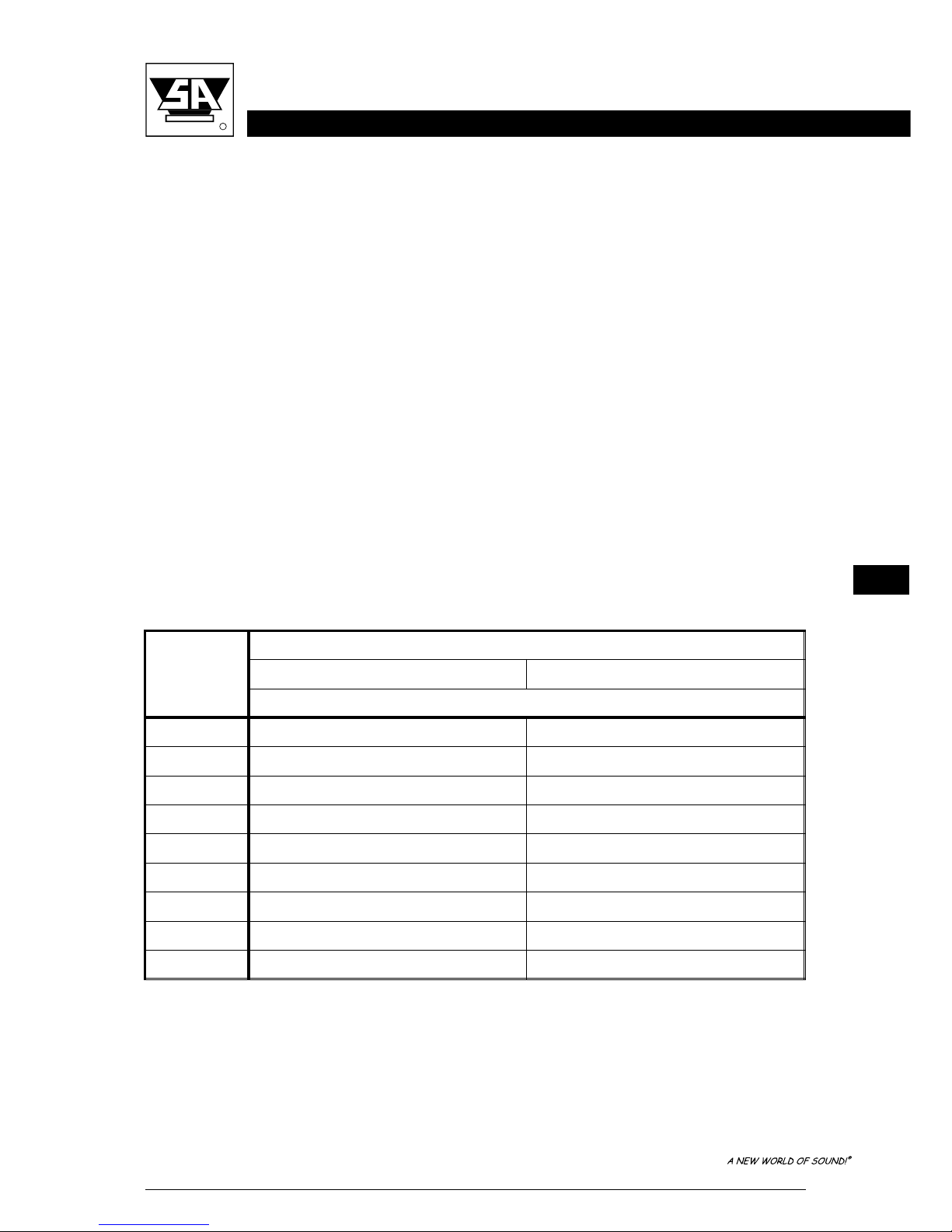
Below, the current consumption of the ES 20 is tabulated for two selectable mains voltages.
The power consumption shown appliesto 1/8 ofmaximumoutput power pinknoisein2 Ω,which
is representative for typical music program with occasional clipping. If your speaker system has
an impedance of 4 or 8 Ωyou may multiply the currents by 0.5 or 0.25.
The mains voltage may NOT deviate more than -20 % to +10 % of the nominal value. The
proportional mains voltage cable loss may not exceed 10 %. The following formula may be used
to calculate the maximum mains cable length in meters for 220-240 V models:
No. ES 20s Mains Voltage (V)
110-120 220-240
Current Consumption (A)
112 6
22412
33618
44824
56030
67236
78442
89648
9 108 54
Table 3-1 Current consumption as a function of the mains voltage at 1/8 of maximum
output power with pink noise in 2 Ω.
CONNECTIONS
stage accompany
R
ES 20 USER MANUAL
3-2
The two input variables are:
N - number of ES 20s supplied through the cable
G - cable gauge in square millimeters
For 110-120 V models the following formula applies:
This means that the cable length is proportional to the cable gauge, while it is inversely
proportional to the number of ES 20s supplied through the cable.
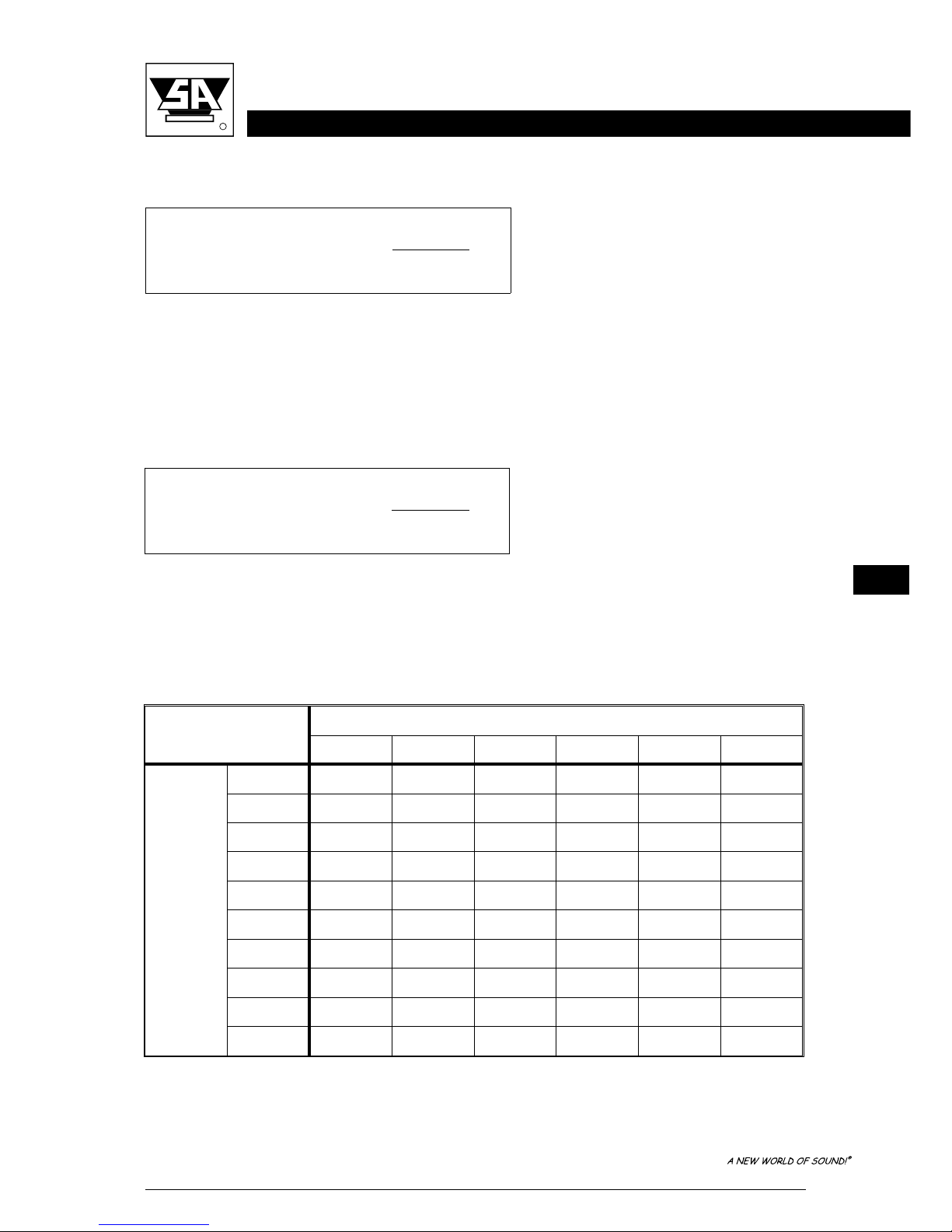
On this and the next page, per mains voltage a table is shown with the maximum mains cable
lengthinmeters,giventhe cablegaugeinsquaremillimetersand thenumberofES20ssupplied
through the cable.
Maximum Length (ML) =
G
*15
N
Maximum Length (ML) =
G
*60
N
110-120 V Cable Gauge (mm2)
1.5 2.5 4.0 6.0 10.0 16.0
No.
of
ES 20s
123386090150240
21119304575120
3 8 13 20 30 50 80
4 6 915233860
5 5 812183048
6 4 610152540
7 3 5 9 13 21 34
8 3 5 8 11 19 30
9 3 4 7 10 17 27
1023691524
Table 3-2 Maximum cable length as a function of the cable gauge and the number of
ES 20s supplied through the cable.
CONNECTIONS
stage accompany
R
ES 20 USER MANUAL
3-3
Indice
Altri manuali Stage Accompany Amplificatore


