Star 025576 Manuale utente

1
© 2021. All rights reserved.
YARD HYDRANTS
MODELS # 025576, 025577,
025578, 025579
Serial Number Purchase Date
Questions, problems, missing parts? Before returning to your retailer, call our customer
service department at 1-800-742-5044, 7:30 a.m. - 5:00 p.m., EST, Monday - Friday.
Please read and understand this entire manual before attempting to assemble, operate, or
install the product.
ATTACH YOUR RECEIPT HERE
SW1682 A
Español p. 10

2
© 2021. All rights reserved.
3
© 2021. All rights reserved.
PACKAGE CONTENTS
WARNING
DESCRIPTION QUANTITY
Yard Hydrant 1
PROP65 WARNING FOR CALIFORNIA RESIDENTS:
Cancer and Reproductive Harm – www.P65Warnings.ca.gov
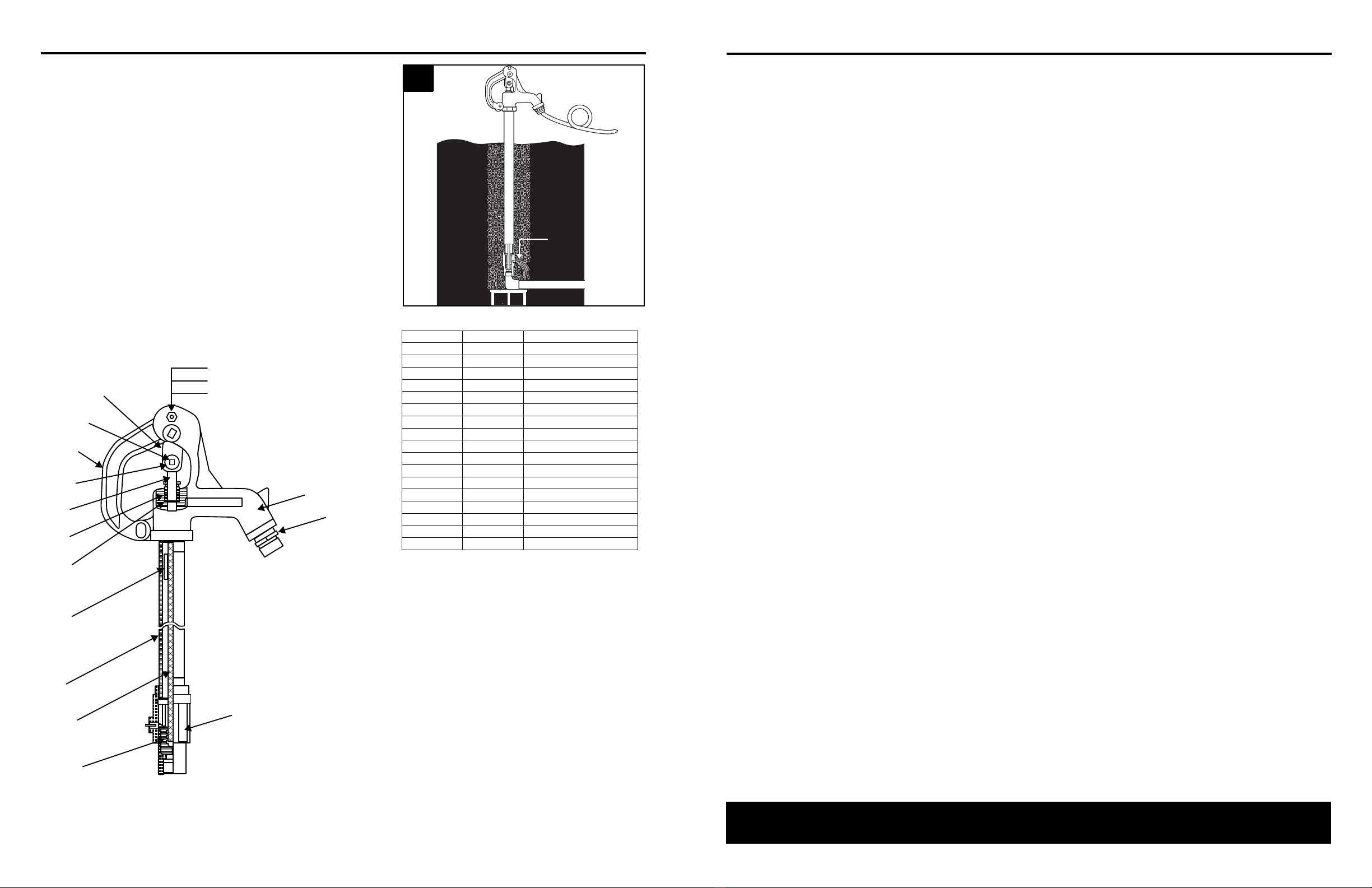
HOW A FROST-PROOF HYDRANT WORKS
2. Watering from the Hydrant
When water is needed, simply lift the hydrant
handle to open the plunger valve until the
desired water ow is obtained.
3. Watering Completed
When the watering project is nished, lower the
handle to close the underground plunger valve.
When the plunger valve closes, it opens a small
drain hole. Water in the hydrant drains from this
hole into the gravel at the base of the hydrant.
Since the hydrant no longer has water above
the frost line, it cannot freeze and is ready for
the next water use.
WATER
DRAINS
OUT HERE
INTO
GRAVEL
FROST
LINE
WATER
SUPPLY
3
DRAIN
PORT
FROST
LINE
WATER
SUPPLY
2
1. How The Hydrant Operates
An easy to use handle controls an underground
plunger valve so water stays below the frost line
until needed.
Adding a bolt or padlock to the convenient
handle loop prevents water loss from vandals or
accidental valve opening by livestock.
A
A
PLUNGER
& VALVE
FROST
LINE
WATER
SUPPLY
1
HYDRANT SPECIFICATIONS
MODEL HYDRANT
LENGTH
RECOMMENDED FOR
FROST DEPTHS OF INLET STAND
PIPE
025576 2 FT. 0-2 FT.
3/4 IN.
FNPT 1 IN.
025577 4 FT. 2-4 FT.
025578 6 FT. 4-6 FT.
025579 8 FT. 6-8 FT.
0-2’
2-4’
4-6’
6-8’
0-2’
2-4’
4-6’
6-8’
SIZING A FROST-FREE HYDRANT
Choose a hydrant length based on the average frost depth in your area (see map below for
approximate depths). The shut-off valve located at the bottom of the hydrant must be installed below
the frost line. If you do not know the local frost depth, contact your local plumbing authority or check
local plumbing codes.

4
© 2021. All rights reserved.
5
© 2021. All rights reserved.
INSTALLATION INSTRUCTIONS Continued
2. Flush piping with water before connecting the
hydrant to clear any gravel or other debris
that may have collected in the piping during
installation and assembly. If not ushed
thoroughly, this debris may jam the hydrant
mechanism or clog the ow ports.
3. Make the pipe connection, but do not bury
the hydrant at this time. Operate the hydrant
to be sure it functions properly and the pipe
connections do not leak. Open and close the
hydrant and check the ow and draining. If
leaks continue from the drain port, see the
following section on HOW TO ADJUST THE
FROST-PROOF YARD HYDRANT.
3
2
Water pressure requirements
Water supply pressure to the hydrant should be regulated at no more than 80 PSI. Higher pressures
will accelerate wear and may cause leakage that will saturate the ground and drain field and prevent
the hydrant from draining. If the hydrant is not allowed to drain, it can freeze and become damaged.
It might also cause flooding and loss of water. High pressure will also cause frequent hydrant
adjustments and lead to increased need for replacement parts. A normal operating pressure should
be 20 to 60 PSI.
NOTE: For installations on a municipal system, you must use a vacuum breaker or backflow device in
accordance with local plumbing codes.
Pipe requirements
160# PSI test pipe is recommended for municipal applications. For most other applications, 100# PSI
plastic coil pipe is recommended.
Drain eld requirements
Saturated ground in the hydrant drain field can prevent the hydrant from draining and may result in
freezing. If the area where the hydrant is located is low lying or has a tendency to collect standing
water, a larger drain field or pit may be required to provide proper draining.
GENERAL INFORMATION
1/8 IN.
DRAINAGE PIPE
WATER SUPPLY
CAUTION: Never leave a hose attached to the hydrant after use. The hose will prevent the hydrant
from draining properly and cause the hydrant to freeze in cold weather. Leaving the hose attached
might also siphon contaminants back into the water system.
Installing hydrant in a building or in asphalt or concrete
If the hydrant will be installed inside a barn or other
structure, or if it is installed in asphalt or concrete such
as a driveway, connect a 1/8” drain pipe or tube to
the drain port and dig a remote drain field outside the
structure for the drain pipe to empty into. Without this
remote piping and drain field, the water from the hydrant
drainage will percolate up to the surface around or near
the hydrant and will damage the flooring or cause muddy
areas in stalls or walkways.
INSTALLATION INSTRUCTIONS
1. Locate the hydrant away from any septic
systems or vehicle trac and convenient for
stock or other watering purposes. Dig a hole for
the hydrant approximately 2 ft. in diameter and
1 ft. deeper than the bury depth.
NOTE: It is helpful to place a brick or cinder block
under the hydrant to support the hydrant and pipe
when the ground settles.
Be sure the total depth of the hole is sucient to
allow the brass valve to be installed below the frost
line. (See local plumbing codes.)
BURY
DEPTH
WATER
SUPPLY
2 FT.
1 FT.
APPROX.
24 IN.
14. Set the hydrant in the hold vertically and ll
the hole around and below the hydrant with
medium size gravel. This will provide a drain
eld for the hydrant. Without a drain eld, the
hydrant will not empty itself and it will freeze
in cold weather. This will damage the hydrant
and cause loss of water and possible ooding
damage.
NOTE: For additional support, install a 4x4 post
next to the hydrant and clamp the pipe to the
post to help keep the hydrant level.
4x4
POST
GRAVEL
4

6
© 2021. All rights reserved.
7
© 2021. All rights reserved.
1. Turn water supply off and open hydrant to
relieve pressure.
2. Close hydrant, then loosen the set screw.
3. Open hydrant to 30 degrees from closed
position.
SET
SCREW
APPROX.
30º
3
SET
SCREW
2
TURN
OFF
WATER
SUPPLY
1
HOW TO ADJUST THE FROST-PROOF YARD HYDRANT
4. Tighten set screw, close the hydrant and turn
water supply on.
5. Operate the hydrant and make sure it is shutting
off and flowing properly.
NOTE: If hydrant does not shut off, repeat steps 1
through 5.
6. Flow water through the hydrant, then close
completely to check for proper drainage by the
following:
a) Listen for water draining down the pipe
b) Putting a hand over the hose connection to feel
for a vacuum. If hydrant does not drain, go to
step 7.
WATER
DRAINS
OUT HERE
INTO
GRAVEL
FROST
LINE
WATER
SUPPLY
6
TURN
OFF
WATER
SUPPLY
5
SET
SCREW
4
HOW TO ADJUST THE FROST-PROOF YARD HYDRANT (Continued)
8
© 2021. All rights reserved.
9
© 2021. All rights reserved.
WARRANTY
This product is warranted for 1 year from date of purchase. Subject to the conditions hereinafter set forth, the
manufacturer will repair or replace to the original consumer, any portion of the product which proves defective
due to defective materials or workmanship. This warranty does not cover replacement parts for failure due to
normal wear and tear. To obtain warranty service, contact the dealer from whom the product was purchased.
The manufacturer retains the sole right and option to determine whether to repair or replace defective
equipment, parts or components. Damage due to conditions beyond the control of the manufacturer is not
covered by this warranty.
THIS WARRANTY WILL NOT APPLY: (a) To defects or malfunctions resulting from failure to properly install,
operate or maintain the unit in accordance with printed instructions provided; (b) to failures resulting from
abuse, accident or negligence or use of inappropriate chemicals or additives in the water; (c) to normal
maintenance services and the parts used in connection with such service; (d) to units which are not installed in
accordance with normal applicable local codes, ordinances and good trade practices; and (e) if the unit is used
for purposes other than for what it was designed and manufactured.
RETURN OF WARRANTED COMPONENTS:
Any item to be repaired or replaced under this warranty must be returned to the manufacturer at Kendallville,
Indiana or such other place as the manufacturer may designate, freight prepaid.
THE WARRANTY PROVIDED HEREIN IS IN LIEU OF ALL OTHER EXPRESS WARRANTIES, AND MAY
NOT BE EXTENDED OR MODIFIED BY ANYONE. ANY IMPLIED WARRANTIES SHALL BE LIMITED TO
THE PERIOD OF THE LIMITED WARRANTY AND THEREAFTER ALL SUCH IMPLIED WARRANTIES ARE
DISCLAIMED AND EXCLUDED. THE MANUFACTURER SHALL NOT, UNDER ANY CIRCUMSTANCES, BE
LIABLE FOR INCIDENTAL, CONSEQUENTIAL OR SPECIAL DAMAGES, SUCH AS, BUT NOT LIMITED TO
DAMAGE TO, OR LOSS OF, OTHER PROPERTY OR EQUIPMENT, LOSS OF PROFITS, INCONVENIENCE,
OR OTHER INCIDENTAL OR CONSEQUENTIAL DAMAGES OF ANY TYPE OR NATURE. THE LIABILITY
OF THE MANUFACTURER SHALL NOT EXCEED THE PRICE OF THE PRODUCT UPON WHICH SUCH
LIABILITY IS BASED.
This warranty gives you specific legal rights, and you may have other rights which vary from state to
state. Some states do not allow limitations on duration of implied warranties or exclusion of incidental or
consequential damages, so the above limitations may not apply to you.
In those instances where damages are incurred as a result of an alleged pump failure, the
Homeowner must retain possession of the pump for investigation purposes.
7. To clear drain hole blockage, close o hydrant
spout by using a hose cap or by attaching and
kinking a hose. Open and close hydrant to allow
water pressure to clear blockage.
Repeat step 6 to verify proper draining. If
hydrant still does not drain, repeat steps 1
through 9 to fully uncover drain hole.
CAUTION: Adjust in small increments. To prevent
over-adjustments and damage to the plunger do
not try to adjust hydrant all at once.
WATER
DRAINS
OUT HERE
INTO
GRAVEL
7
HOW TO ADJUST THE FROST-PROOF YARD HYDRANT
7
6
5
4
8
9
10
11
12
13
14
15
16
17
1
2
3
ITEM QTY DESCRIPTION
1 1 Foot valve
2 1 Hose adapter
3 1 Head
4 1 Bolt
5 1 Nut
6 1 Snap washer
7* 2 Linkage
8* 1 Square head set screw
9 1 Handle
10* 1 Connector
11 1 Clevis rod
12* 1 Packing nut
13* 2 O rings
14 1 Coupling nut
15 1 Pipe
16 1 Inner rod
17* 1 Plunger
*These items are included in repair kit # 025580
Questo manuale è adatto per i seguenti modelli
3
Indice
Altri manuali Star Pompa dell'acqua

Star
Star STL001 Manuale utente

Star
Star ES05S Manuale utente

Star
Star STPP15VS Manuale utente

Star
Star 5STH Schema elettrico

Star
Star S1108 Manuale utente

Star
Star 3STHALC Manuale utente

Star
Star 148004 Manuale utente

Star
Star CS511 Manuale utente

Star
Star 148014 1HP Manuale utente

Star
Star SPCP01 Manuale utente


Manuali Pompa dell'acqua popolari di altre marche


Sykes AmeriPumps
Sykes AmeriPumps GP100M Guida alla risoluzione dei problemi

DUROMAX
DUROMAX XP WX Series Manuale utente

BRINKMANN PUMPS
BRINKMANN PUMPS SBF550 Manuale utente

Franklin Electric
Franklin Electric IPS Manuale utente

Xylem
Xylem e-1532 Series Manuale utente

Milton Roy
Milton Roy PRIMEROYAL Manuale utente