Stewart Filmscreen Cabaret Guida rapida


Installation Instructions
Cabaret Electriscreen: Owner’s Manual 1
Inspect :
Inspect the box for obvious damage.
Make sure the product box was delivered
in proper condition and all the fragile
labels were honored. If the box looks to
be in bad shape; straps are broken,
corners caved in, or there are obvious
bends or intrusions in the cardboard
packing material, please indicate the
damage clearly on the Bill of Lading
before signing and accepting shipment
or refusing. Please inspect the product
within 48 hours of receipt. If damage is
observed please call your dealer or
Stewart Filmscreen Corp immediately.
Leave the product in the package
unless advised to remove it.
Cut :
To insure that the product is safe inside,
do not attempt to rip or pull off the straps.
This will most likely damage the packing
box and/or the product components.
Open :
Remove tape and staples.
Fold the box open and look inside.
Nylon straps are to be cut only.
Confirmation :
Locate both shipping labels to insure that
the correct product was delivered to the
correct person/company/corporation.
Also, the top main label has the product
weight information on it. Be sure to use
proper lifting techniques to avoid injury
to personnel or damage to the box
and product.
01
02
03
04

Installation Instructions
Cabaret Electriscreen: Owner’s Manual 2
Check:
Inside the box are the main Cabaret
unit, the LED light bar (OPTIONAL),
the controls and the owner’s manual.
Unwrap :
Be sure to read this instruction
manual completely before
proceeding.
Gently, remove the protective wrap off
LED lighting if applicable. Insure that
the LED lighting looks in good order.
Removal :
Remove the Cabaret unit from the box.
Be sure to use proper lifting techniques
to avoid injury. Cabaret unit should be
lifted straight up and out of the box.
Avoid turning the unit on end.
Control box :
The Cabaret screen and optional
LED bar are supplied with
independent control systems.
Check your order and verify that the
correct controls were sent to you.
05
07
06
08

Installation Instructions
Cabaret Electriscreen: Owner’s Manual 3
Packing Removal :
Remove the packing material from
the unit by sliding the end packing
and center support packing off.
Remove plastic wrap and stretch
wrap from unit. Do not remove
batten retainers at this time.
Mounting location:
Determine where you want the top
of the projected image to be.
Y= amount of top masking.
X= Y(top masking)+6 5/8”(case height)
Z= amount of space for LED light wash.
If the unit has LED bar, then Z=
6 Inches or more of clearance.
Wall types :
Determine the type of
wall construction.
Mounting Options:
The Cabaret screen is available with
either the standard mounts, close
coupled slide and lock plates, or the
extended mount kit, which cantilevers
the unit out from the wall to clear a flat
panel display, an art work or other
wall décor. If you have the standard
mounts proceed to the next step, for
extended mounts, go directly to page 6.
10
12
09
11

Installation Instructions
Cabaret Electriscreen: Owner’s Manual 4
Mounting hardware :
(Hardware not included)
Determine suitable anchors for your
wall type.
Each anchored screw should support
a minimum of 65lbs (30kgs)
Masonry mount :
The first hole is determined by the
projected image in relationship to the
mounting hole on the Cabaret unit
(reference image 11). After finding the
screw hole location, drill, mount anchor,
and screw the screw in the wall about
90%. Leave space for the keyhole on the
unit to slide over the screw freely.
Drywall mount :
The first hole is determined by the
projected image in relationship to the
mounting hole on the Cabaret unit
(reference image 11).
Find your stud location, and slide
the Cabaret mounting bracket to match
the keyhole to the first mounting hole.
After determining your screw hole
location, drill, mount anchor, and screw
the screw in the wall about 90%,
leave space for the keyhole on the
unit to slide over the screw freely.
13
16
123
14
123
(z) LED Lighting Space
(+/-) In between
Mounts Distance
(x)Top of Image to Hole
15
(z) LED Lighting Space
(+/-) In between
Mounts Distance
(x) Top of Image to Hole
Hit Wood!

Installation Instructions
Cabaret Electriscreen: Owner’s Manual 5
Mounting the unit :
Caution: Now that the front cover is
removed, do not handle the screen
material or batten, only touch the case.
Place the unit on the screw in the first
hole anchor. With the unit attached to
the first anchor, swivel the Cabaret unit
using the spirit levelers as a guide to
find the position of the second hole and
mark the location. Remove the unit off
the wall now, place it away from the
work area so no damage can be done
to the screen material or the case.
Proceed to mount a screw in the second
hole position. Reference images 14-16
for help if needed. Now with the unit in
the desired location tighten both screws
down to secure the Cabaret unit in place.
20
Front valance removal :
Swivel the valance outward on the top
hook rail, and then lift the valance
away from the unit.
Caution: Do not pull on the valance from
the center of the unit to try to release it,
this may cause damage to the unit.
Remove acrylic top piece and protective
paper. To remove the front valance
place your hands at the very ends of the
unit, reach inside the batten cutout with
your hands and pull down to release
the cover.
17
18
Batten packing removal :
With the front valance removed proceed
to remove batten retaining foam blocks.
19

Installation Instructions
Cabaret Electriscreen: Owner’s Manual 6
Attach clip to end of wall plate with
two 1/4-20 hardware provided.
Align the ledger edges of the clip
upward as shown.
B4
Reference image #13
(Hardware not included)
Locate wall studs. The center of the
bracket should be no more than 6 inches
away from the end of the backbone rail.
Two holes of the wall plate must be
mounted to a stud or otherwise suitably
anchored. The other two holes should
be secured to the wall. Mount wall plate
to wall using appropriate hardware.
Placing Cover :
Slide plastic cover over the
plate and snap it into place.
B3
Offset Bracket :
The offset bracket comes in 3 pieces.
The Wall Plate, plastic cover, and clip.
Decide how you are going to wire the
unit. Wiring may optionally run through
the offset bracket into a wall box.
The slot on the wall plate is for optional
wire routing. This slot must be oriented
either up or down.
B1
B2

Installation Instructions
Cabaret Electriscreen: Owner’s Manual 7
Locating the ILC Board :
If you have a Cabaret unit with LED
lighting, look to locate your Integrated
Lighting Control (ILC) board placed
inside the cast aluminum end pice on
the audience right of the Cabaret unit.
IMC and ILC Communication:
If you purchase you lighting kit from
Stewart after the purchasing of the unit,
pay close attention to the next steps.
Caution: Unplug unit power if applicable
before you work on wiring the IMC or ILC.
Do to the fact that the Cabaret Unit has
active lighting on deploy & retract, the
IMC has to interface with the ILC via a
RJ25 (low voltage) cable as seen in the
image on the left and in the next image.
ILC (Intelligent Lighting Control):
Using the diagram on the left, you can
get familiar with the wiring of the ILC
which controls the LED lighting.
21
22
Mounting Unit :
Clip the Cabaret back rail to
the mount.
Secure clip to unit, using the provided
1/4-20 Screws and a 5/32 size Allen key.
B5
LED Option Only
23
Installation Instructions
Cabaret Electriscreen: Owner’s Manual 8
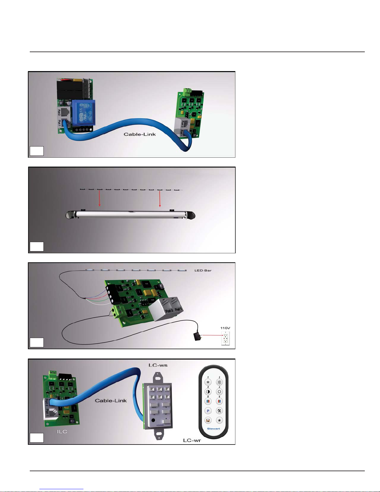
LED lighting :
If you have a light bar, place it on top
of the support brackets inside of the
Cabaret unit. The leads for the LED
strip should be on the audience right
unless otherwise specified.
LED Controls :
The LED lighting can be powered up
only on screen deployment or retraction,
if no LED control component are added
to the system; With the LC (Light Control)
wall switch (WS) or (WR) wireless remote
control, you can fully configure the LED
strip by changing; colors and intensity.
Consult your LED Lighting manual on full
details of operation and settings.
Powering up the lighting :
Using the diagram on the left, wire up
the ILC by first connecting in the LED
lighting bar into the board and than the
transformer into a 110V wall socket.
RJ25 (low voltage) Cable Link :
Connect the IMC board to the ILC board
by using a RJ25 cable. Use Connection
port (#1) on the IMC and port (#1)
on the ILC.
If you purchase the unit with LED lighting
then this connection will be made at the
factory.
24
25
26
27
Indice
Altri manuali Stewart Filmscreen Accessori


