STOKVIS ENERGY SYSTEMS R40 EVO 60 Manuale utente

R40 (Evolution Range)
MODUPAK
CASCADE ASSEMBLY
MANUAL
STOKVIS ENERGY SYSTEMS
Unit 34 Central Park Estate
34 Central Avenue
West Molesey
Surrey
KT8 2QZ
Tel: 020 8783 3050
Fax: 020 8783 3051
E-Mail:
Website:
info@stokvisboilers.com
www.stokvisboilers.com
420010768400 04/2016 – Doc195-V1.0

2

3
Contents
Technical data ................................................................................... 4
Declaration of Conformity ................................................................................... 7
Cascade assembly General instructions ................................................... 8
Frame - line, wall mounted......................................... 9
Frame - line, floor standing frame............................... 10
Frame - back to back, floor standing frame................ 11
Collector..................................................................... 12
Boilers........................................................................ 13
Insulation - back panel ............................................... 14
ISPESL kit (Italy only)................................................. 15
Gas filter..................................................................... 16
Low loss header......................................................... 17
Plate heat exchanger ................................................. 17
Boiler connection kit - line .......................................... 18
Boiler connection kit - back to back............................ 19
Boiler pump - high efficiency speed controlled........... 20
Insulation - front panel................................................ 21
Insulation - end pieces ............................................... 23
Insulation - connection piece 2 collectors................... 25
Insulation - back to back panel................................... 26
Air inlet cover ............................................................. 27
Flue system - line....................................................... 28
Flue system - back to back......................................... 29
Controls...................................................................... 30
Dimensions DN65 line + low loss header....................................... 31
DN100 line + low loss header..................................... 32
DN65 back to back + low loss header........................ 33
DN100 back to back + low loss header...................... 35
DN65 line + plate heat exchanger.............................. 35
DN65 back to back + plate heat exchanger................ 36
Component index System components................................................... 37
Insulation.................................................................... 41
Controls...................................................................... 41
Flue system................................................................ 43
Boiler connection kits ................................................. 44
Boiler pumps .............................................................. 45
Boiler accessories...................................................... 46
4
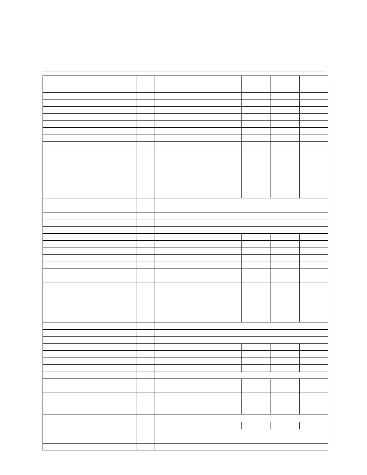
Technical data
R40 EVO
60
.
R40 EVO
70
.
R40 EVO
80
.
R40 EVO
100
.
R40 EVO
120
.
R40 EVO
140
Nominal heat output at 80/60°C max/min kW 56,5/15,5 65,5/15,6 75,3/19,4 92,9/18,7 111,9/22,5 130,4/26,2
Nominal heat output at 50/30°C max/min kW 60,4/17,2 70,0/17,2 79,7/21,2 98,9/20,6 118,5/24,8 137,8/28,9
Nominal heat output at 40/30°C max/min kW 60,5/17,3 70,0/ 17,4 79,7/21,5 98,9/20,9 118,5/25,2 137,8/29,3
Nominal heat input Hi max/min kW 57,9/16,0 66,8/16,0 76,8/19,8 95,2/19,0 114,3/22,9 133,3/26,7
Modulation ratio - 3,6 4,2 3,9 5 5 5
Efficiency at 80/60°C max/min % 97,6/97,0 98,0/97,5 98,0/97,9 97,6/98,3 97,9/ 98,3 97,8/ 98,3
Efficiency at 50/30°C max/min % 104,4/107,4 104,8/107,3 103,8/107,2 103,9/108,5 103,7/108,4 103,4/108,3
Efficiency at 40/30°C max/min % 104,5/108,3 104,8/108,5 103,8/108,6 103,9/110,0 103,7/109,9 103,4/109,8
Efficiency at 36/30°C load 30% % 107,2 107,2 107,1 107,8 107,9 107,6
RAL 40/30 average % 108,7 109,1 109,4 109,4 109,1 108,7
Heat Loss (Pstby) W 81 81 81 92,7 92,7 92,7
Max. condensate flow l/h 3,6 4,4 4,3 5,4 6,4 7,1
Gas consumption G20 max/min (10,9 kWh/m3) m3/h 5,3/1,5 6,1/1,5 7,0/1,8 8,7/1,7 10,5/2,1 12,2/2,4
Gas consumption G25 max/min (8,34 kWh/m3) m3/h 6,9/1,9 8,0/1,9 9,2/2,4 11,4/2,3 13,7/2,7 16,0/3,2
Gas consumption G31 max/min (12,8 kWh/kg) kg/h 4,5/1,3 5,2/1,3 6,0/1,5 7,4/1,5 8,9/1,8 10,4/2,1
Gas pressure G20 mbar 20
Gas pressure G25 mbar 25
Gas pressure G31 mbar 30/50
Maximum gas pressure mbar 50
Max. temperature flue gas (high limit) °C 90
Flue gas temperature at 80/60°C max/min °C 59/57 60/57 61/58 60/56 63/56 66/57
Flue gas temperature at 50/30°C max/min °C 43/35 44/34 45/33 44/33 46/33 48/33
Flue gas temperature at 40/30°C max/min °C 42/33 44/33 44/33 43/32 45/32 47/32
Flue gas temperature at 36/30°C load 30% 34 35 35 33 34 35
Flue gas quantity max/min m3/h 83/22 98/22 113/27 139/27 168/33 202/38
CO level at 80/60 °C max/min ppm 75/11 92/11 87/7 67/5 82/4 62/7
CO level at 80/60 °C max/min mg/kWh 80/11 99/11 94/7 72/5 88/5 67/7
CO year emission EN15502 ppm 35,79 43,76 51,73 41,53 40,76 39,99
CO year emission EN15502 mg/kWh 38,44 47 55,56 44,6 43,78 42,95
CO2 level Max. Load G20-G25 % 8,5(+0-0,2) 8,4 (+0-0,2) 8,4 (+0-0,2) 8,4 (+0-0,2) 8,4 (+0-0,2) 8,2 (+0-0,2)
CO2 level Min. Load G20-G25 % 9,0 (+0-0,2) 9,0 (+0-0,2) 9,0 (+0-0,2) 8,5 (+0-0,2) 8,5 (+0-0,2) 8,5 (+0-0,2)
Restriction ∆CO2 max.load - min. load (G20- % - - - - - <0,3
CO2 level Max. load % 9,6 (0 +0,2)
CO2 level Min. load % 9,6 (0 +0,2)
Restriction ∆CO2 max.load - min. load % CO2 Min. load ≤CO2 Max. load
NOx level at 80/60 °C max/min ppm 25/1030/1134/1625/1122/1515/15
NOx level at 80/60 °C max/min mg/kWh 44/1753/1960/2844/1938/2726/26
NOx emission EN15502 ppm 13,94 18,78 23,61 28,38 22,61 16,84
NOx emission Hi/Hs EN15502 mg/kWh 24,60/22,15 32,61/29,36 40,61/36,57 46,67/42,03 38,19/34,40 29,71/26,76
NOx class EN15502 6
Max. permissible flue resistance Pa 167 200 200 173 134 200
Water volume l 6 6 6 9 9 9
Water pressure max/min bar 08/01 08/01 08/01 08/01 08/01 08/01
Max. water temperature (High limit thermostat) °C 100 100 100 100 100 100
Maximum temperature setpoint °C 90 90 90 90 90 90
Nominal water flow at dT=20K m3/h 2,4
Hydraulic resistance at nominal flow rate kPa 15 18 22 7 9 11
Electrical connection V 230
Frequency Hz 50
Mains connection fuse A 10
5
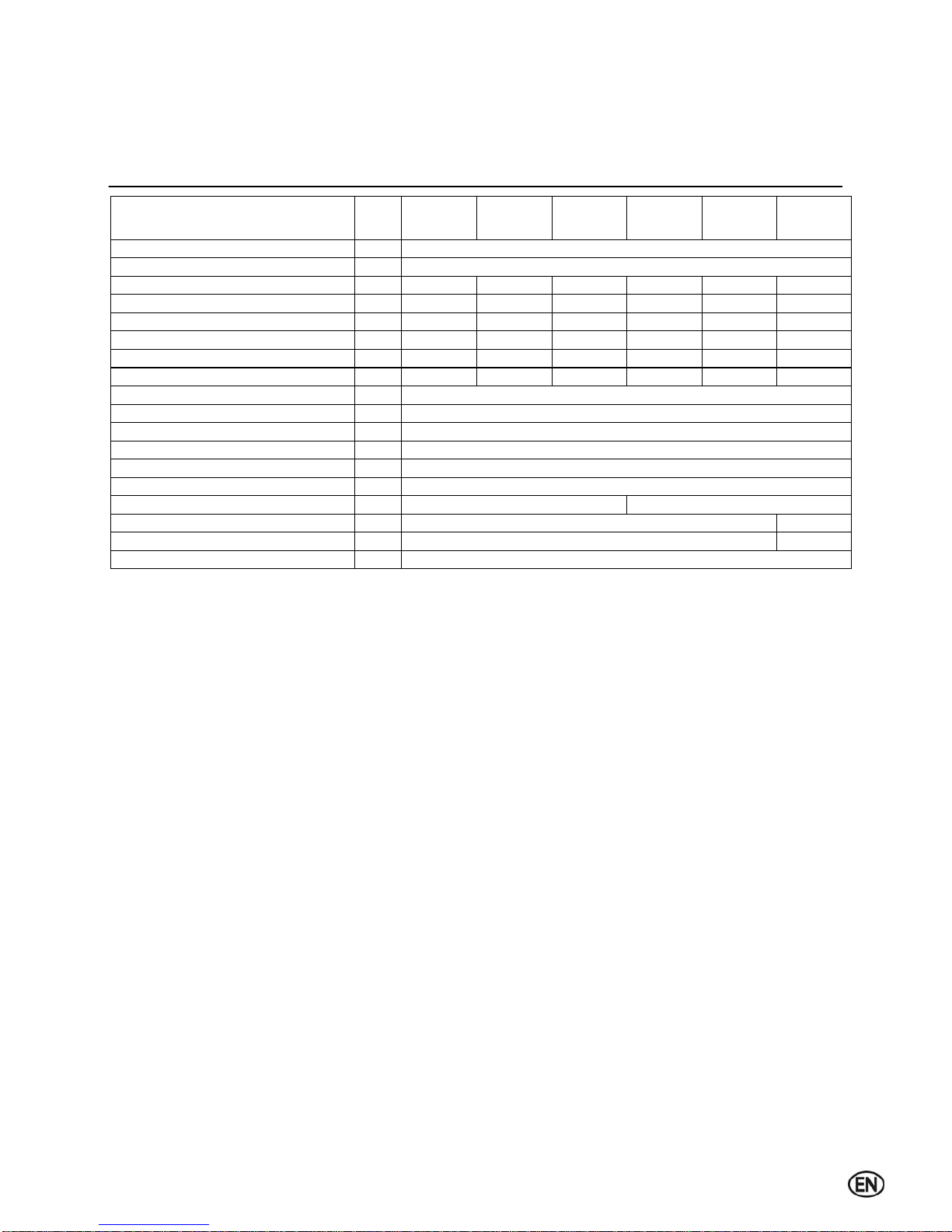
Technical data
R40 EVO
60
.
R40 EVO
70
.
R40 EVO
80
.
R40 EVO
100
.
R40 EVO
120
.
R40 EVO
140
IP class with App. Type
C13, C33, C43, C53, C63, C83,
-
Weight (empty) Kg 83 83 83 96 96 96
Weight (filled with water) Kg 89 89 89 105 105 105
Sound Power Level (LWA) dB 55 55 56 62 57 57
Ionisation current μA 1,15 1,15 1,15 4,2 1,15 4,2
Rpm max / min load G20-G25 rpm 6070/1770 7260/1800 7820/2060 6710/1570 4960/1150 5730/1300
Rpm pre / post purge rpm 2800/2800
pre / post purge time sec 10-30
safety time sec 5
pH value condensate - 3,2
CE certification code - CE-0063CM3576
Water connections - R1.1/2”
Gas connection - R3/4” R1”
Flue gas connection (DN) - 100 130
Air intake connect. (room sealed use) (DN) mm 100 130
Condensate connection mm 22
IPX4D
IP class with Appliance Type B23(P) - IP30
Rpm max / min load G31 rpm 5810/1770 6710/1800 7190/2060 6090/1570 4690/1150 5460/1300
6
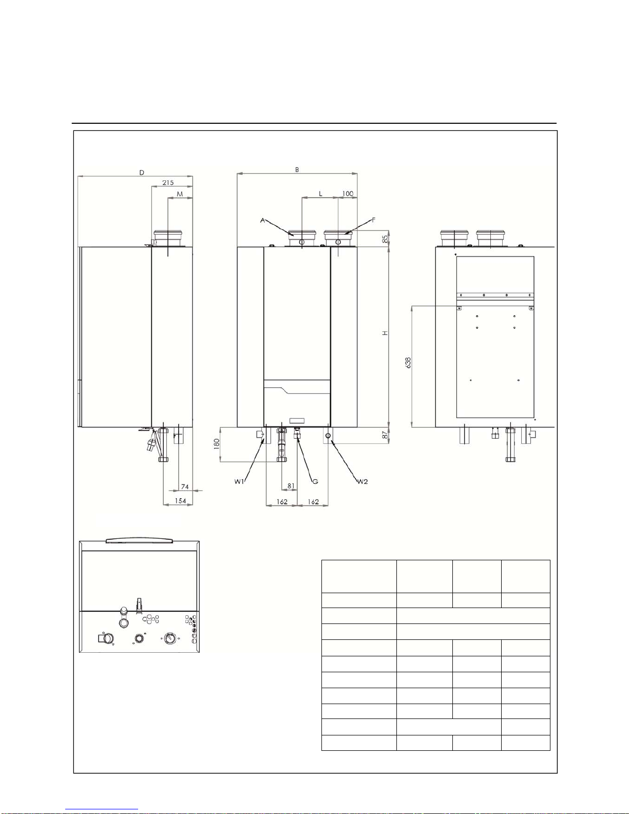
Technical data
Dimensions
R40 EVO
60/70/80
.
R40 EVO
100/120
.
R40 EVO
140
A mm 100
100 130
B mm 630
D mm
H mm 810 950 950
W1 mm R1.¼ R1.½ R1.½
W2 mm R1.¼ R1.½ R1.½
G mm R¾ R1 R1
F mm 100 100 130
L mm 140 190
M mm 115 115 130
605
Side view Front view Back view
Bottom view

7
Declaration of Conformity
Declaration of Conformity
Elco BV, Hamstraat 76, 6465 AG Kerkrade (NL),
Declares that the products
R40 EVO
Is in conformity with the following standards:
EN 15502-1
EN 15502-2-1
EN 55014-1 / -2
EN 61000-3-2 /-3
EN 60 335-1/ -2
And in accordance with the guidelines of directives:
92 / 42 / EEC (boiler efficiency directive)
2009 / 142 / EEC (gas appliance directive)
2006 / 95 / EEC (low voltage directive)
2004 / 108 / EEC (EMC directive)
2014 / 68 / EU PED directive, art. 4-3
2009 / 125/ CE Energy related Products
811-813 / 2013 EU regulation
This product is designated with CE number:
CE - 0063CM3576
Kerkrade, 01-03-2016
A.J.G. Schuiling
Plant Manager

8
Cascade assembly
General instructions
The following pages show the most
convenient way to install the complete
cascade system, both for line and back to
back solutions.
The pictures show a cascade system with
system connections to the right, but it’s
also possible to make the system
connections to the left.
The system should be installed and
commisioned by authorized personnel
only.
The usage of approved sealing material
is highly recommended.
After assembly, the system should be
pressure tested to check if the assembly
is done in a proper way and the system is
not showing any leakages (hydraulics
and gas!).
This manual is purely meant to assist to
the installation of a complete cascade
system. For technical details about the
boilers or system components, please
refer to the boiler manual or planner
documentation.
9
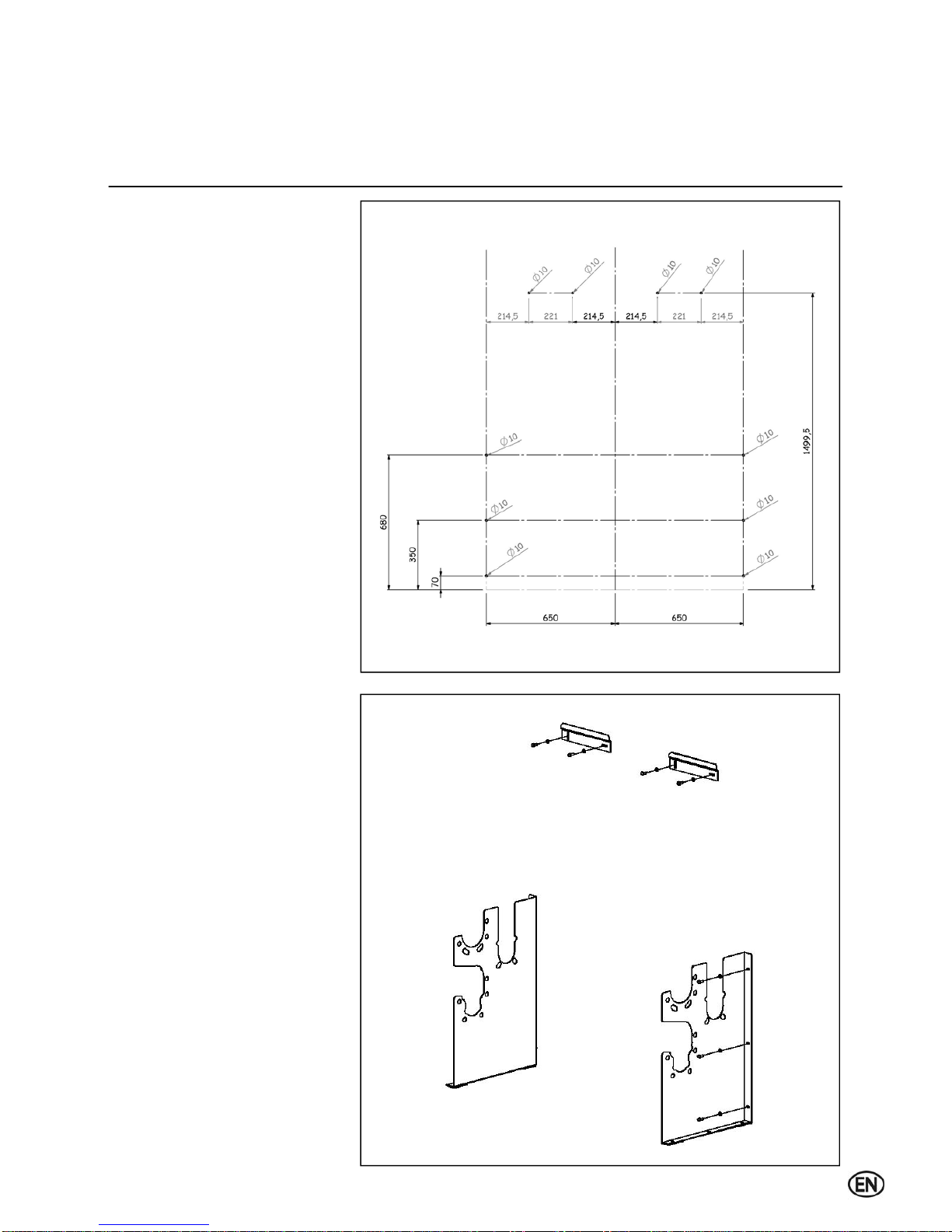
Cascade assembly
Frame - line, wall mounted
Mark the boreholes on the wall as
displayed in the drawing.
Drill the holes and place the plugs.
NOTE:
Before installing the boilers on the wall,
please ensure that the wall is firm enough
to carry the weight of the boilers (see
technical data for weight indication by
boiler type).
Fix the boiler supports and collector
support panels to the wall.
10
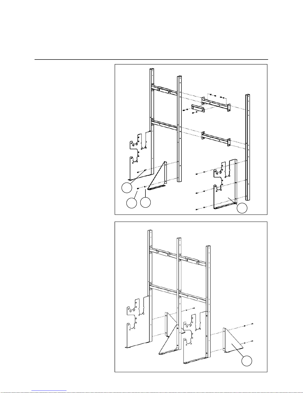
Cascade assembly
Frame - line, floor standing frame
Place the frame on a clean and level
surface.
All parts are assembled and fastened
with M8 hexagonal bolts (1) and
washers (2) .
The collector supports (3) and (4) are
designed for both frame support as well
as support for the hydraulic and gas
collector tubes.
Assemble the back feet (5) for more
stability when the system is free standing
in the boiler room.
3
4
1 2
5
Questo manuale è adatto per i seguenti modelli
5
Indice


