
Strong Super Trouper Manuale utente

FOLLOW SPOTLIGHT
INSTRUCTION MANUAL
4350 McKinley Street • Omaha, Nebraska 68112 USA
Tel (402) 453-4444 • Fax (402) 453-7238 • www.strong-lighting.com
Equipment Type 7201156 • Rev. October 2010


PREFACE
THESTRONGXENONSUPERTROUPER®isadirectcurrentfollowspotlight
systemcompletewithaxenonlamphouse,powersupply,opticalsystem,andaoorstandandyoke
assembly.Anoptionalsix-color,selfcancellingboomerang(OrderNo.7201188;seeFigure7)may
beorderedwithnewequipment,oritcanbeaddedatalaterdate.
ONLY THE SPECIAL XENON POWER SUPPLIES manufactured by Strong
Internationalcanbeusedwiththexenonspotlight.
Forinstallationandoperationofthepower
supply,seetheinstructionmanualfurnishedseparately.
THEXENONLAMPHOUSEutilizesadeepellipsedichroicmetalreectordesignedto
operateinaxedpositionwithahorizontallymountedxenonbulbasthelightsource.Aheatlteris
locatedinthefrontofthelamphousetoreducetheheatattheopticalsystemandcolorboomerang.
ONLY XENON BULBS designed for horizontal operation should be used in this
spotlight.Thelamphouseisdesignedforusewiththestandard2000watthorizontaltheatrebulb,
andanoptionalAdapterKit(OrderNo.7201192)allowsuseof1000and1600wattbulbs.Seethe
listinginthismanualfortheapprovedtypesandnecessaryadapters.
ADJUSTMENTCONTROLforpositioningthexenonbulbislocatedattherearof
thelamphouse.Theadjustmentsareforthehorizontal,vertical,andfocuscontrolofthebulb.
THELAMPHOUSE INSTRUMENTPANELisequipped withan ammeterand
runningtimemeter.Theammeterindicatestheoperatingcurrentofthelamp,andtherunningtime
meterrecordsthenumberofhoursthelamphasoperated.Thexenonbulbisignitedandextinguished
byuseoftheLAMPswitchmountedontheinstrumentpanel.
THELAMPBLOWER,internallywiredinthelamp,operateson115V.ACandis
requiredtokeep thesealson thebulbatasafeoperatingtemperature. Thisblower willoperate
continuouslyuntilpoweristurnedoffatthemainlineswitchtothexenonpowersupply.Anair
owswitchinthelamphousepreventsoperationofthexenonlampiftheblowerisnotoperating,or
ifairowisinadequate.Ifadditionalcoolingisrequired(i.e.50Hertzpowersource),anoptional
ExhaustBlowerAssembly(7201036;seeFigure8)maybemountedtothetopofthelamphouse.
THELAMPHOUSEissuppliedwitha11foot(3.35m)cablecontainingthetwoDC
leads,thegroundlead,andallACcontrolleads.Thecableterminatesinamultiple-pinMSconnector
tomatetoacorrespondingreceptacleonthexenonpowersupply.
WHENTRANSPORTINGthefollowspotlight,itisrecommendedthatthexenonbulb
beremovedfromthelamphouseandplacedinitsoriginalshippingcartonwiththeprotectivecover
onthebulbtopreventbreakage.
XST/001
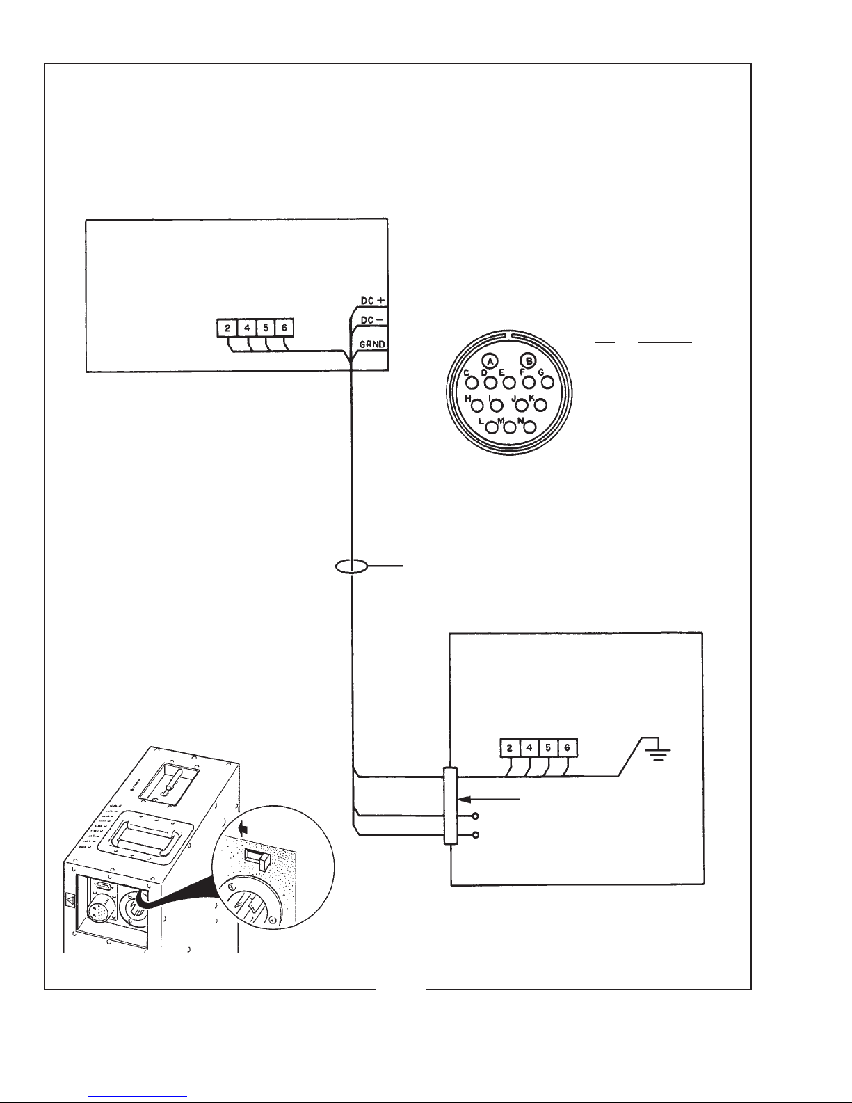
LAMPHOUSE - POWER SUPPLY
Interconnection Diagram
LAMPHOUSE
(Connections Pre-wired)
MS CONNECTOR
Pin Wire No.
A DC-
B DC+
C 2
E 4
F 5
G 6
M Grnd
Lamphouse
Cable Assembly
XENON
POWER
SUPPLY
MS Connector (pre-wired)
DC+
DC-
XST/002
SYSTEM MUST BE GROUNDED
All wiring must conform to local codes;
shield lamphouse cable in conduit if
required.
Check Slide Switch (below) on Power
Supply for correct “SPOT” position.
Slide to LEFT

XST/003
INSTALLATION AND SETTING UP SPOTLIGHT
THEXENONSUPERTROUPERisshippedinsectionswhichmustbeassembled.
TheFoldingBaseStandAssembly65826000(seeFigure6)isshippedcollapsed,andrequiresonly
foldingdownandpinningthefourbaselegs.
WHENINSTALLEDinapermanentlocation,thelevelingfeetmustberemoved,and
theclearanceholesinthebaselegbracketsusedforhardware(usersupplied)toboltthebasetothe
oororplatform.Ifitisdesiredtohavetheunitportable,whenoperating,thelevelingfeetmustbe
adjusteddownuntiltheweightofthespotlighthasbeenshiftedfromthecasterstothelevelingfeet.
THEINNERTUBEandsupportyokehasthreeholestopermitadjustingtheheightof
thespotlight.Thethreeholesareonfour-inchcentersandwillallowanopticalheightofapproximately
53inches,57inches,and61inchesaboveoorleveltotheopticalcenterofthelamphouseandlens
system.Thelevelingfeetmaybeadjustedthroughanadditionaltwoinchrange.Inserttheheightloca-
tionpin(Figure5,Item16)throughtheholeintheoutertubeandoneoftheholesintheinnertube.
THEHORIZONTALSWINGandverticaltiltlockingknobsareontherighthand
(operating)sideoftheyokeassembly.Tightenbothoftheselockingdevices(Figure6,Items19&
21)securelybeforeattemptingtoplacethelamphouseandlenssystemonthesupportyoke.
PLACETHELAMPHOUSEandlenssystemontheyokeassembly(Figure6,Item4),
withthespotsizecontrolhandletotherighthand(operating)side,thesameasthelockingcontrols
ontheyoke.Lineupthefourmountingholesinthebottomofthebaserailwithfourslottedholesin
thesupportyokeandsecurewiththefour5/16-18wingscrews.Thereare(2)setsoffourmounting
holestoinsurecorrectbalanceofthespotlightwithorwithouttheoptionalcolorboomerang.An
optionalCounterweightKit(7201191)isalsoavailableforsettingconcisebalanceadjustments.
THEOPTIONALCOLORBOOMERANG(7201188)mountstothefrontopening
oftheopticalsystemonthreestudsprotrudingfromthefrontoftheopticalsystemhousing.Secure
theboomerangusingthe(3)screwsprovided,andinstallthesafetycablebetweentheboomerang
housingandthespotlightframe.
ATTACHTHELAMPHOUSECABLECONNECTORtothereceptacleonthexenon
powersupply.Alignthepinsbeforetighteningthelockingring.Donotenergizethepowersupply
beforerstcompletingthebulbinstallationprocedure.
CHECKTHE“CONS/SPOT”SLIDESWITCHonthexenonpowersupplycabinet
andverifythatithasbeenplacedintheappropriate“SPOT”position.Seetheillustrationonthe
insidefrontcoveroftheXenonPowerSupplyinstructionmanual.
SAFETY PROCEDURES
THEXENONBULBishighlypressurized.Whenignited,thenormaloperatingtemperature
ofthebulbincreasesthepressuretoalevelatwhichthebulbmayexplodeifnothandledinstrictaccordance
tothemanufacturer’soperatinginstructions.Thebulbisstableatroomtemperature,butmaystillexplodeif
droppedorotherwisemishandled.
REFERbulbreplacementandservicetoQUALIFIEDPERSONNELwithadequateprotec-
tiveclothing(faceshield,cleancottongloves,welder’sjacket).Forroutinelamphouseservice,observethe
followingrules:
1. Allowthebulbtocooltoroomtemperaturebeforeopeningthelamphouse.Putonprotectiveclothing
describedabove.
2. De-energizethexenonpowersupplyattheACsourcebeforeopeningthelamphousecompartment.
3. Whenpossible,encasethe bulb in its protectivecover whencleaning orservicing the lamphouse
interior.Thebulb,whenoutsidethelamphouse,mustbeencasedinthecover.
4. Cleanthebulbafterithascooledtoroomtemperature.Donottouchthequartzenvelopeofthebulb;
ngerprintswillburninandcreatehotspotswhichmayshortenbulblife.Ifngermarksaremade,
theyshouldbecarefullyremovedwithmethylalcoholandcottonpriortobulboperation.
5. Neverviewanignitedbulbdirectly.BLINDNESSORPERMANENTEYEDAMAGEMAYBE
INCURRED.
6. UseonlyxenonbulbsdesignatedasOZONEFREE.Whenpossible,ventthelamphouseexhaustto
outsideatmosphere.
7. Maintainthelamphousebloweringoodoperatingcondition.Keeptheblowerinletcleanforunre-
strictedairow.
8. Toinsuremaximumbulblife,operatethelamphouseblowerandtheexhaustsystemforat leastten
minutesafterextinguishingthebulb.
9. Ifreturningabulbforwarrantyadjustment,packitinitsoriginalshippingcontainer.Completeand
returnallrequiredwarrantyinformation.
10. Disposeofexpiredbulbsthatarebeyondwarrantyinthefollowingmanner:Wrapthebulbtightly
inseverallayersofcanvasorheavycloth.Placeitonahardsurfaceandshattertheenvelopewitha
sharphammerblow.DONOTplaceanunshatteredbulbinanordinaryrefusecontainer.
11. DONOTPERMITUNAUTHORIZEDPERSONNELTOPERFORMORATTEMPTANYPHASE
OFXENONBULBHANDLINGORSERVICE.
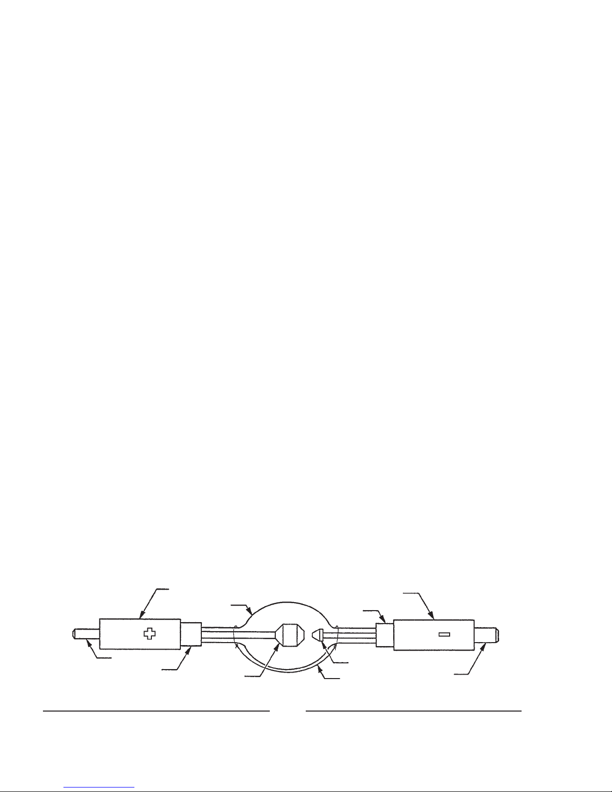
Cathode End Cap
Envelope
Anode End Cap
Anode Pin
Seal Anode
Cathode
Trigger Wire Cathode Pin
Seal
XST/004
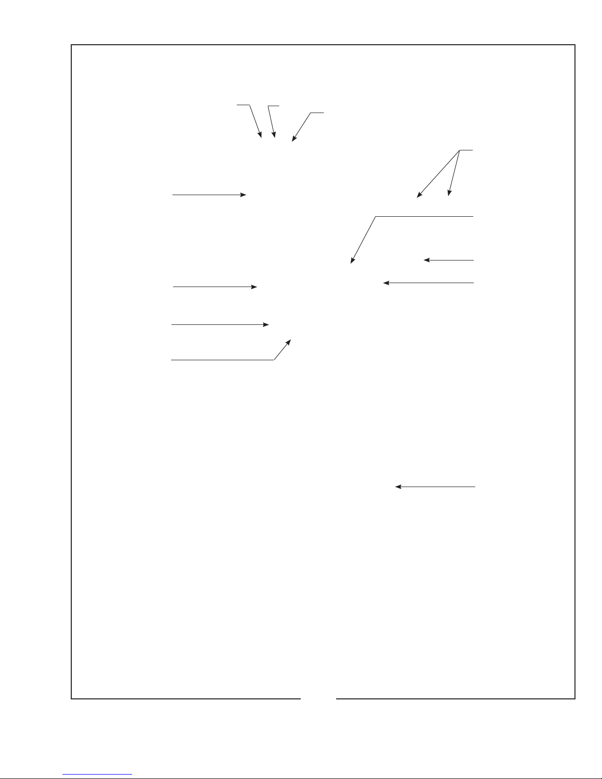
1.Fade-OutMechanismControlLever
2.MaskingShutter(Chopper)ControlLever
3.IrisControlLever
4.BoomerangMountingStud,Upper*
5.SpotSizeControlHandle
6.BoomerangMountingStud,Lower*
XST/005
2
13
4
5
6
7
8
9
10
11
12
7.SpotFocusControlKnob
8.LevelingFoot
9.HeightAdjustPin
10.HorizontalSwingControlLever
11.VerticalTiltControlLever
12.LiftingStrap
*ColorBoomerangoptional;seeFigure7

EXHAUST SYSTEM INSTALLATION
IFTHESPOTLIGHTisinstalledinaclosedbooth,itisrecommendedtoventthe
lamphouseexhausttooutsideatmospheretoremovetheheatfromthebooth.Anoptionallamphouse
topcoverplatewithanexhauststack(PartNo.7201222)maybeorderedfromStrongandinstalled
inplaceofthestandardtopcoverplate(seePartsList,Figure2,Item27).
THEEXHAUSTSTACKoftheoptionallamphousecoverplateisdesignedtota
six-inchdiameterduct.Theexhaustsystemmustbedesignedandinstalledisamannerastoelimi-
nateanypossibilityofadowndraftorofraindrippingintothelamphouse.Theexhaustfanmustbe
capableofremoving750linealfeetperminute(150cfm)ofairfromeachlamphouse.
TO PERMIT MOVEMENT of the follow spotlight, install a section of six-inch
diameter,non-ammable,exibleductingbetweenthelamphouseexhauststackandtheprojection
boothexhaustsystem.Twoscrewholesintheexhauststackcanbeusedtosecuretheductingwith
#6self-tappingsheetmetalscrews.
IFADDITIONAL BULB COOLING is required (i.e. 50 Hertz power source), an
optionalExhaustBlowerAssembly(PartNo.7201036;seeFigure8)maybemountedtotheexisting
topcoverofthelamphouse.Whenconnectingtheblowerleads,makecertainthewiresaredressed
behindthereectorsupportcastingtopreventheatdamage.Thisblowerassemblyexhaustsintothe
surroundingairanddoesnotallowconnectiontoaductedexhaustsystem.
THERADIATIONfromsomexenonbulbscanconverttheoxygeninthesurrounding
airtoozone.Inlargequantities,ozonecanendangerhealth,butitspontaneouslychangesbackinto
oxygeninaveryshorttime,especiallyifitmixeswithalargevolumeofair(asinanauditorium,
arena,oroutdoors).Mostcurrentlymanufacturedxenontheaterbulbsareclassiedasozone free
anddonotreleaseozone.
XST/006
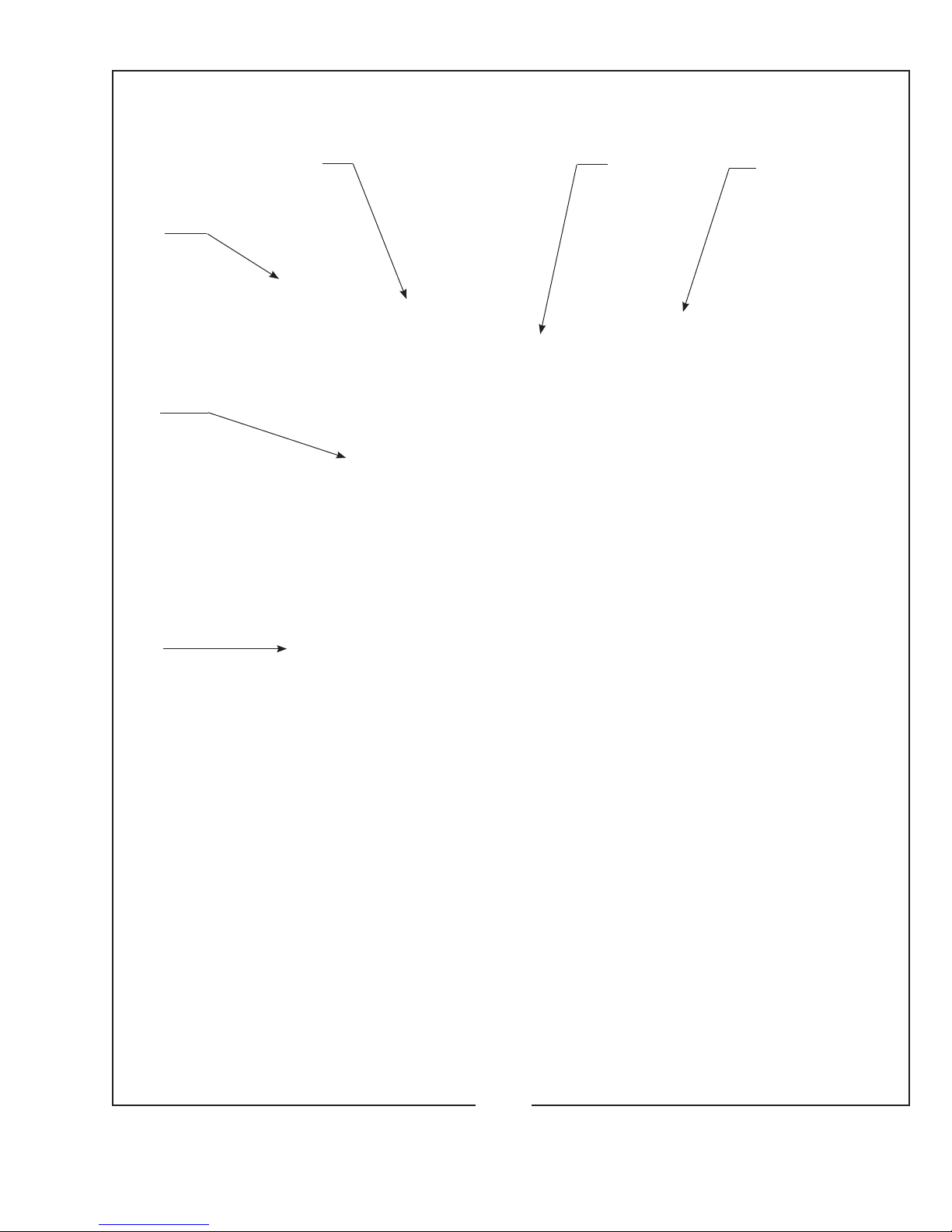
1.LAMPSwitch(ON-OFF)
2.Ammeter
3.AirIntake,Blower
4.Cover,BulbAdjustControls
5.TopCover,Lamphouse
6.ElapsedHourMeter
XST/007
12
3
4
5
6
XST/008
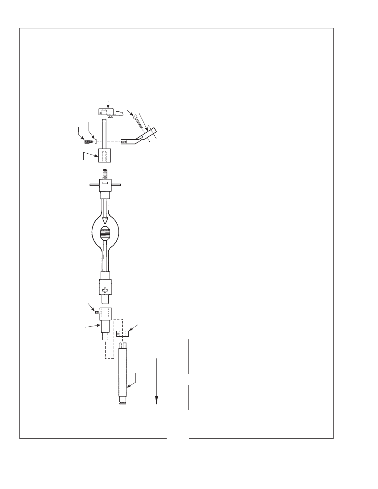
1000, 1600 WATT BULB INSTALLATION
Requires optional Bulb Adapter Kit 7201192
65960000* 65131000
4100180
65199000
REAR OF LAMPHOUSE
OBSERVE CORRECT POLARITY
65117000*
4110750
65198000 65152A00
65151000
65148000*
1000 Watt Operation: 50 Amperes Nominal
DO NOT EXCEED 58 AMPERES
1600 Watt Operation: 65 Amperes Nominal
DO NOT EXCEED 70 AMPERES
PartNo. Description
65117000 BulbSupportYoke
65131000 Anode(+)ContactClamp
65148000 Cathode(-)ContactClamp
65151000 RetainerPlate
65152A00 Thumbscrew(2req’d.)
65198000 CathodeAdapter
65199000 AnodeAdapter
65960000 RearBulbSupportCollet
4080870 ClampingScrew(for65131000&65148000)
4100180 SetScrew,AnodeAdapter
4110750 BulbSupportMountingScrew
4250373 LeadMountingScrew(for65131000&65148000)
NOT SHOWN
65948000 Negative(-)LeadAssembly,29"(ClamptoShunt)
65966000 Positive(+)LeadAssembly(incl.65131000)
* Replace Collet, Front Bulb Support, and
Cathode Clamp before installing bulb.
Indice
Altri manuali Strong Attrezzatura di illuminazione


