Studio Technologies 206 Manuale utente

Copyright © 2020 by Studio Technologies, Inc., all rights reserved
www.studio-tech.com
User Guide
Issue 3, August 2020
This User Guide is applicable for serial numbers
M206-00501 and later with application firmware 1.4 and later
and STcontroller application version 2.04.00 and later.
50646-0820, Issue 3
Model 206 Announcer’s Console

This page intentionally left blank.

Model 206 User Guide Issue 3, August 2020
Studio Technologies, Inc. Page 3
MODEL 206
ANNOUNCER’S CONSOLE
Table of Contents
Revision History ........................................................... 4
Introduction ................................................................... 5
Getting Started ............................................................. 10
Operation ...................................................................... 19
Technical Notes ............................................................ 24
Specifications ............................................................... 28
Appendix A: Model 206 Block Diagram ........................ 29

Issue 3, August 2020 Model 206 User Guide
Page 4 Studio Technologies, Inc.
MODEL 206
ANNOUNCER’S CONSOLE
Revision History
Issue 3, August 2020:
• Documents addition of Main Out Tally function. (Applies only to serial numbers
M206-00501 and later.)
Issue 2, October 2018:
• Documents addition of the Push to Mute/Tap to Latch main button operating mode.
Issue 1, April 2018:
• Initial release.
Model 206 User Guide Issue 3, August 2020
Studio Technologies, Inc. Page 5
MODEL 206
ANNOUNCER’S CONSOLE
Introduction
The Model 206 Announcer’s Console of-
fers a unique combination of analog and
digital audio resources for use in broadcast
sports, eSports, live event, entertainment,
and streaming broadcast applications. The
unit is housed in a compact, rugged steel
enclosure that’s intended for table-top
use. Calling the Model 206 “cute” or “cool”
would be accurate; its nicely proportioned
but diminutive size makes it ideal for use
in space-constrained locations. The Model
206 supports Dante® audio-over-Ethernet
digital media technology with AES67 com-
patibility for integration into contemporary
applications. The unit is extremely simple
to deploy, is “pro” quality throughout, and
provides an intuitive user experience. The
Model 206’s audio quality is excellent, with
low distortion, low noise, and ample head-
room. Careful circuit design and rugged
components ensure long, reliable operation.
The Model 206 integrates directly into both
Dante audio-over-Ethernet and standard
analog audio environments. With just a
Power-over-Ethernet (PoE) connection, a
microphone, and a pair of headphones or
an earpiece, a complete broadcast on-air
position can be created. And by using the
Model 206’s microphone output a direct
connection to an analog microphone-level
input on an associated camera, remote I/O
interface, or audio console can be support-
ed. Two remote control inputs allow external
switches or contact closures to activate the
main and talkback button functions. One of
the inputs can also be configured to provide
a low-voltage DC “tally” output that follows
the state of the main output.
Model 206 operating features are config-
ured using the STcontroller personal com-
puter software application. An extensive set
of parameters allows the unit’s functions to
be tailored to meet the needs of many ap-
plications. STcontroller is a fast and simple
means of confirming and revising the unit’s
operating parameters.
Applications
The Model 206 on its own can provide an
“all-Dante” solution for one on-air talent
location. A wide range of applications can
be supported, including sports and enter-
tainment TV and radio events, streaming
broadcasts, corporate and government AV
installations, and post-production facili-
ties. The unit’s small size makes it ideal for
live-sports applications, such as basketball,
where physical space for personnel is very
limited. Four Dante receiver (audio input)
channels supply the user with their talent
cue (IFB) signals. Should the cue signal
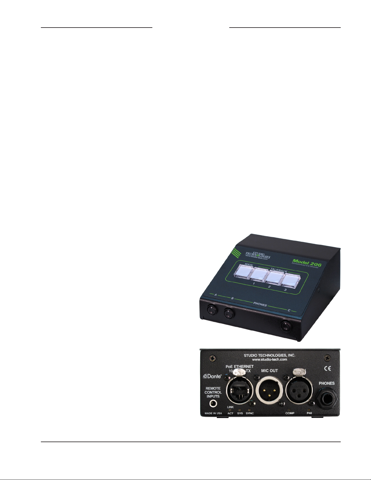
Figure 1. Model 206 Announcer’s Console front
and rear views

Issue 3, August 2020 Model 206 User Guide
Page 6 Studio Technologies, Inc.
MODEL 206
ANNOUNCER’S CONSOLE
be “mix-minus” an integrated sidetone
function can provide the user with a micro-
phone confidence signal. Four Dante audio
output channels, one designated as main
and three named talkback, are routed via
an associated local-area network (LAN) to
inputs on Dante-compatible devices. Four
pushbutton switches, main and three talk-
back, provide the user with direct control
over audio routing. The audio switching is
performed in the digital domain and is virtu-
ally “click-free.”
By providing the main audio signal in two
forms, Dante digital audio and analog
microphone level, the Model 206 makes
integration into a wide range of on-air envi-
ronments easy to accomplish. And with the
three talkback audio channels available as
Dante output channels, routing to inputs on
a variety of devices, such as matrix inter-
com systems, audio consoles, and monitor
loudspeaker systems, is simple and flexible.
Some applications may benefit from not
utilizing the Model 206’s Dante main output
channel. This typically won’t be an issue
of inadequate audio quality but rather a
need to match work-flow requirements. For
example, for lip-sync or transmission pur-
poses it may be optimal to have the on-air
audio transported as an embedded signal
along with the associated camera video. Al-
ternately, all on-air audio sources may need
to connect to inputs on an audio console or
console-related I/O unit. Supporting these
scenarios is not a problem as the Model
206 supplies a microphone output connec-
tion that’s specifically intended for this pur-
pose. Simply connect the unit’s microphone
output connection to the desired analog
input, such as the mic/line input on an ENG-
style camera—that’s it!
The circuitry associated with the Model
206’s analog microphone output is very sim-
ple, essentially a passive path that routes
a signal connected to the microphone input
connector directly to the microphone output
connector. A solid-state circuit, in series
with the mic in-to-mic out path, allows mut-
ing of the signal on the microphone output
connector whenever the Dante main output
channel is muted. Having both the Dante
main output and the microphone outputs
work in tandem can be a valuable resource,
allowing one to serve as the primary on-air
signal source while the other serves as the
backup.
Setup and Operation
Set up, configuration, and operation of the
Model 206 is simple. An etherCON® RJ45
jack is used to interconnect with a standard
twisted-pair Ethernet port associated with
a PoE-enabled network switch. This con-
nection provides both power and bidirec-
tional digital audio. A broadcast headset
or handheld (“stick”) microphone can be
directly connected to the unit’s 3-pin XLR
mic input connector. The input is compatible
with dynamic or condenser microphones.
The integrated P48 phantom power source
provides support for a wide range of con-
denser microphones. A 3-pin XLR micro-
phone output connector provides a “direct
mic out” function for integration with micro-
phone inputs on related devices. Stereo
headphones, the headphone connections
from a stereo or monaural headset, or even
a monaural earpiece can be connected to
the phones output jack.
External switches or contact closures can
be connected to the Model 206’s remote
control inputs to allow activation of the
main and talkback button functions. A low-
voltage/low-current DC output can also

Model 206 User Guide Issue 3, August 2020
Studio Technologies, Inc. Page 7
MODEL 206
ANNOUNCER’S CONSOLE
be implemented providing a Main Out Tally
function. The STcontroller software applica-
tion is used to configure the wide range of
Model 206 operating parameters. This al-
lows the unit’s performance to be optimized
to meet the needs of specific applications.
The user is presented with four pushbutton
switches and three push-in/push-out rotary
level potentiometers This makes it easy to
control the status of the main and talkback
outputs as well as adjusting the signals that
are sent to the headphone channels.
Ethernet Data and PoE
The Model 206 connects to a local area net-
work (LAN) by way of a standard 100 Mb/s
twisted-pair Ethernet interface. The physical
100BASE-TX interconnection is made by
way of a Neutrik® etherCON RJ45 connec-
tor. While compatible with standard RJ45
plugs, etherCON allows a ruggedized and
locking interconnection for harsh or high-
reliability environments.
The Model 206’s operating power is provid-
ed by way of the Ethernet interface using
the 802.3af Power-over-Ethernet (PoE)
standard. This allows fast and efficient inter-
connection with the associated data net-
work. To support PoE power management,
the Model 206’s PoE interface enumerates
(reports) to the power sourcing equipment
(PSE) that it’s a class 2 (low power) device.
If a PoE-enabled Ethernet port can’t be
provided by the associated Ethernet switch
a low-cost PoE midspan power injector can
be utilized.
Dante Audio-over-Ethernet
Audio data is sent to and received from
the Model 206 using the Dante audio-over-
Ethernet media networking technology.
As a Dante-compliant device, the Model
206’s four Dante transmitter (audio output)
channels and four Dante receiver (audio
input) channels can be assigned (routed
or “subscribed”) to other devices using the
Dante Controller software application. The
Dante transmitter and receiver channels
are limited to supporting four Dante flows,
two in each direction. The digital audio’s
bit depth is up to 24 with a sampling rate of
44.1 or 48 kHz. Two bi-color LEDs provide
an indication of the Dante connection sta-
tus. An additional LED displays the status
of the associated Ethernet connection.
The Model 206 is compatible with the
AES67 interoperability standard. In this
mode the four transmitter (output) channels
will function in multicast; unicast is not sup-
ported. In addition, the unit is compatible
with the Dante Domain Manager™ (DDM)
software application.
Audio Quality
The Model 206’s audio performance is
completely “pro.” A low-noise, wide dy-
namic-range microphone preamplifier and
associated voltage-controlled-amplifier
(VCA) dynamics controller (compressor)
ensures that mic input audio quality is
preserved while minimizing the chance of
signal overload. The output of the micro-
phone preamp and compressor is routed
to an analog-to-digital conversion (ADC)
section that supports sampling rates of 44.1
and 48 kHz with a bit depth of up to 24.
The audio signal, now in the digital domain,
routes through a 32-bit microprocessor and
on to the Dante interface section where it is
packetized and prepared for transport over
Ethernet.
Audio input signals arrive via the four Dante
receiver channels and pass into the Model
206’s microprocessor. The supported sam-
pling rates are 44.1 and 48 kHz with a bit
depth of up to 24. Channel routing, head-

Issue 3, August 2020 Model 206 User Guide
Page 8 Studio Technologies, Inc.
MODEL 206
ANNOUNCER’S CONSOLE
phone level control, and sidetone creation
are performed within the digital domain. This
provides flexibility, allows precise control,
and keeps the three level potentiometers
from having to directly handle analog audio
signals. The audio channels destined for the
phones outputs are sent to a high-perfor-
mance digital-to-analog converter and then
on to robust driver circuitry. High signal lev-
els can be provided to a variety of headsets,
headphones, and earpieces.
Configuration Flexibility
The Model 206 can be configured to meet
the needs of specific applications and user
preferences. All configuration choices are
performed using the STcontroller personal
computer software application. There are no
mechanical switch settings or button-press
sequences required to configure how the
unit functions. Selectable parameters include
microphone preamplifier gain, P48 phantom
power on/off, button operation, remote con-
trol inputs (included tally output), headphone
output mode, sidetone operation, and overall
unit operation. The gain of the microphone
preamplifier can be selected from among
four choices. This allows the Model 206 to
match the output sensitivity of a range of
handheld and headset-associated micro-
phones. A low-noise source of P48 phantom
power can be enabled if required to support
condenser (capacitor) microphones.
The main and talkback pushbutton switches
can be individually configured. The main but-
ton can be selected to operate from among
five modes while the talkback buttons can be
selected from among three. These choices
allow the Model 206’s operation to be tai-
lored to meet the specific needs of many ap-
plications. As an example, for on-air sports
applications the main button would typically
be configured to provide a push to mute
(cough) function. The microphone signal
on the Dante main output channel and the
microphone output connector would remain
active unless the talent needs to momen-
tarily disable it. The talkback buttons would
most likely be set to their push to talk modes
as their use would be intermittent.
The Model 206 provides two remote control
inputs. Configuration choices allow these
to be assigned to work in parallel with the
main or talkback pushbutton switches. In
this way, activation of a remote control input
will emulate a user pressing its associated
pushbutton switch. Remote Control Input 1
can also be configured to provide a Main Out
Tally function.
The audio sources and the way in which
they are assigned to the headphone output
channels can be configured from among five
choices. These unique choices allow almost
any required headphone monitoring situa-
tion to be implemented. Whether for use in
on-air sports, an awards show broadcast, or
as a production support tool, the Model 206
should be able to achieve the desired con-
figuration.
Following the mode number is an abbrevi-
ated description of what signal or signals are
assigned to the three potentiometers (pots)
and on to the two headphone output chan-
nels. The potentiometers are labeled A, B,
and C, as can be seen in Figure 1 of this
guide. The format would equate to Mode x
– pot A/pot B/pot C where x equals the mode
number.
• Mode 1 – Ch1L/Ch2R/SidetoneLR:
Provided for broadcast applications where
two monaural channels of talent cueing
audio (“IFB”) need to be independently
sent to the left and right headphone out-
put channels. It would be common for
program audio with director interrupt to

Model 206 User Guide Issue 3, August 2020
Studio Technologies, Inc. Page 9
MODEL 206
ANNOUNCER’S CONSOLE
enter the Model 206 by way of Dante
input (receiver) channel 1 and be sent to
the left headphone output. Program-only
audio, entering the unit by way of Dante
input channel 2, would be sent to the right
headphone output. Pots A and B are used
to adjust the level of those signals. Pot C
is used for the sidetone function where mi-
crophone audio is sent to both the left and
right channels of the headphone output.
• Mode 2 – Ch1LCh2R/BalanceLR/
SidetoneLR: Intended for applications
where a stereo signal enters the Model
206 by way of Dante inputs 1 and 2 and
is routed in stereo to the left and right
channels of the headphone output. In this
mode pot A controls the overall level of
this stereo signal and the pot B controls
its left/right level balance. Pot C is used by
the sidetone function.
• Mode 3 – Ch1LCh2R/Ch3LCh4R/
SidetoneLR: Allows two stereo signals to
be routed as stereo pairs to the two head-
phone output channels. In this mode pot A
adjusts the level of the stereo pair entering
the unit by way of Dante inputs 1 and 2
while pot B adjusts the level of the stereo
pair entering on Dante inputs 3 and 4. Pot
C is used by the sidetone function.
• Mode 4 – Ch1L/Ch2R/Ch3LCh4R:
Allows two monaural input signals to be
independently routed to the left and right
headphone output channels. These audio
signals would enter the Model 206 by way
of Dante input channels 1 and 2. Pots A
and B are used to control the levels of the
signals as they are sent to the left and
right headphone output channels. A stereo
input signal, entering the unit by way of
Dante inputs 3 and 4, are routed to the left
and right headphone outputs. The level of
this stereo pair is controlled by pot C.
• Mode 5 – Ch1LR/Ch2LR/Ch3LCh4R:
Allows two monaural input audio chan-
nels to be sent to both the left and right
headphone output channels. Dante inputs
1 and 2 are used to bring these audio
signals into the Model 206. Pots A and B
are used to control the level of the signals
as they are sent to the headphone output
channels. Pot C is used to control the level
of a stereo input signal as it is routed to
the left and right channels of the head-
phone output. This stereo pair enters the
unit by way of Dante inputs 3 and 4.
The integrated sidetone function can be con-
figured to operate from among four choices.
This allows audio associated with the micro-
phone input and microphone preamplifier to
be returned to the headphone output. This
is important as different applications may
provide a “full mix” or a “mix-minus” talent
cue signal. If a full mix cue signal is provided
then sidetone audio will not be needed and
the function can be disabled. In the case
where a mix-minus signal is present, provid-
ing the user with sidetone at the appropriate
time(s) can be an important means of con-
firming the signal that’s coming from the con-
nected microphone.
The headphone gain range configuration
helps to provide an optimized audio level to
Model 206 users. The appropriate setting will
depend on the specific audio sources pro-
vided to the unit as well as user preference.
Three system modes select the overall way
in which the Model 206 functions. The on-
air mode is optimized for applications where
users will be on-air talent that must maintain
strict separation between on-air and produc-
tion audio channels. Other applications will
benefit from the two available production
modes.

Issue 3, August 2020 Model 206 User Guide
Page 10 Studio Technologies, Inc.
MODEL 206
ANNOUNCER’S CONSOLE
Future Capabilities and
Firmware Updating
The Model 206 was designed so that its
capabilities and performance can be en-
hanced in the future. A USB connector,
located on the unit’s main circuit board
(underneath the unit’s cover), allows the ap-
plication firmware (embedded software) to
be updated using a USB flash drive.
The Model 206 uses the Audinate Ultimo™
integrated circuit to implement the Dante
interface. The firmware in this integrated
circuit can be updated via the Ethernet con-
nection, helping to ensure that its capabili-
ties remain up to date.
Getting Started
What’s Included
Included in the shipping carton are a Model
206 Announcer’s Console and a printed
copy of this guide. As a device that is
Power-over-Ethernet (PoE) powered, no
external power source is provided. In most
applications an Ethernet switch with PoE
capability will be utilized. If that’s not avail-
able a PoE midspan power injector can be
used.
Connections
In this section signal interconnections will
be made using the five connectors located
on the back of the Model 206’s enclosure.
An Ethernet data connection with Power-
over-Ethernet (PoE) capability will be made
using either a standard RJ45 patch cable or
an etherCON protected RJ45 plug. A mi-
crophone will be connected using a cable-
mounted 3-pin male XLR connector. A set
of headphones or an earpiece will be con-
nected by way of a ¼-inch plug. If desired,
the Model 206’s microphone-level output
may be interfaced with other equipment
using a cable terminated with a standard
3-pin female XLR connector. Special ap-
plications may utilize the two remote control
inputs that are accessible using a 3.5 mm
3-conductor jack. Remote Control Input 1
can be configured such that it provides a
tally output.
Ethernet Connection with PoE
A 100BASE-TX Ethernet connection that
supports Power-over-Ethernet (PoE) is
required for Model 206 operation. This one
connection will provide both the Ethernet
data interface and power for the Model
206’s circuitry. A 10BASE-T connection is
not sufficient and a 1000BASE-T (“GigE”)
connection is not supported unless it can
automatically “fall back” to 100BASE-TX op-
eration. The Model 206 supports Ethernet
switch power management, enumerating
itself as a PoE class 2 device.
The Ethernet connection is made by way of
a Neutrik etherCON protected RJ45 con-
nector that is located on the back of the
Model 206’s enclosure. This allows connec-
tion by way of a cable-mounted etherCON
connector or a standard RJ45 plug. The
Model 206’s Ethernet interface supports
auto MDI/MDI-X so that a “cross-over” or
“reversing” cable will never be required.
Ethernet Connection without PoE
As previously discussed in this guide, the
Model 206 was designed such that the
Ethernet connection will provide both data
and Power-over-Ethernet (PoE) power.
There may be situations where the as-
sociated Ethernet switch does not provide
PoE power. In such cases an external PoE
midspan power injector can be used. If the
selected midspan power injector is 802.3af-
compatible it should function correctly.
Altri manuali per 206
2
Questo manuale è adatto per i seguenti modelli
1
Indice
Altri manuali Studio Technologies Attrezzatura per DJ


