Sumec 5554-747 Manuale utente

After-sales Service Guide
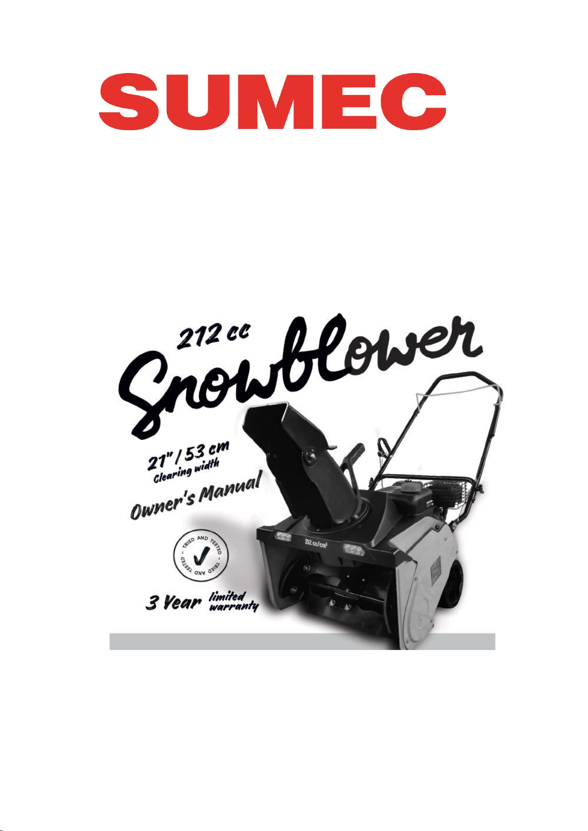
21" 212cc Snow blower
SAN: 0533201847ZB
Customer Model: 5554-747

2
CONTENTS
Specification 3
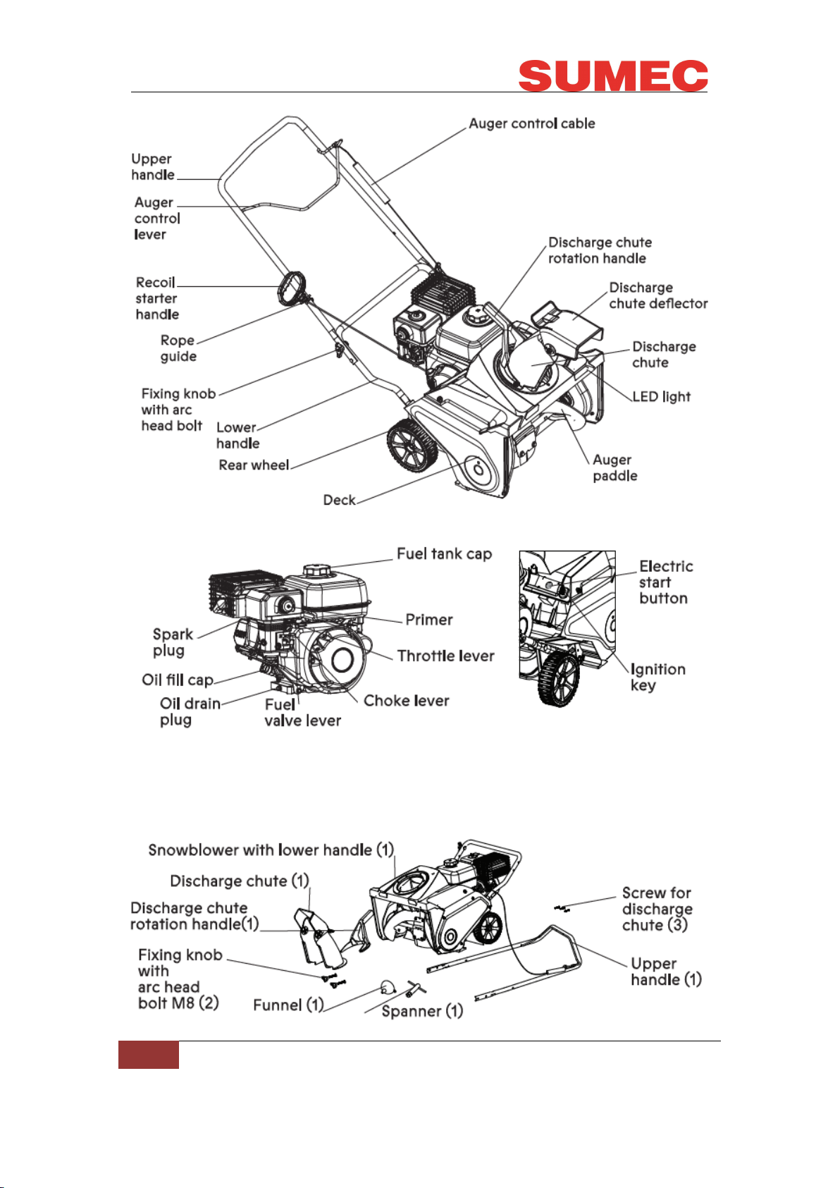
Main parts Location 3
BOM& Spare Parts List 5
Operating Instructions 5
Maintenance and Storage 13
FAQS 20

3
Specification
Main parts Location

4
PARTS LIST
Carefully remove the machine from its packaging and check that the following
parts are included:

5
BOM& Spare Parts List
See Appendix 1.
Operating Instructions
ASSEMBLY
IMPORTANT! THIS SNOWBLOWER IS SHIPPED WITHOUT OIL OR
GASOLINE IN THE ENGINE.
Your new snowblower has been assembled at the factory with the exception of
those parts left disassembled tor shipping purposes. All parts such as nuts,
washers, bolts, etc., necessary to complete the assembly have been placed in
the parts bag. To ensure safe and proper operation of your snowblower, all
parts and hardware you assemble must be tightened securely. Use the correct
tools as necessary to ensure proper tightness.
TO REMOVE SNOWBLOWER FROM CARTON
1. Remove loose parts included with snowblower.
2. Cut down two end corners of carton and lay end panel down flat.
3. Remove all packing materials except padding between upper and lower
handle and padding holding operator presence control bar to upper handle.
4. Roll snowblower out of carton and check carton thoroughly tor additional
loose parts.
ASSEMBLING THE UPPER HANDLE
1. Position the ends of the upper handle on the inside of the lower handle and
align the holes.
2. Insert the arc head bolt into the aligned holes, with the bolt heads on the
inside of the handle.
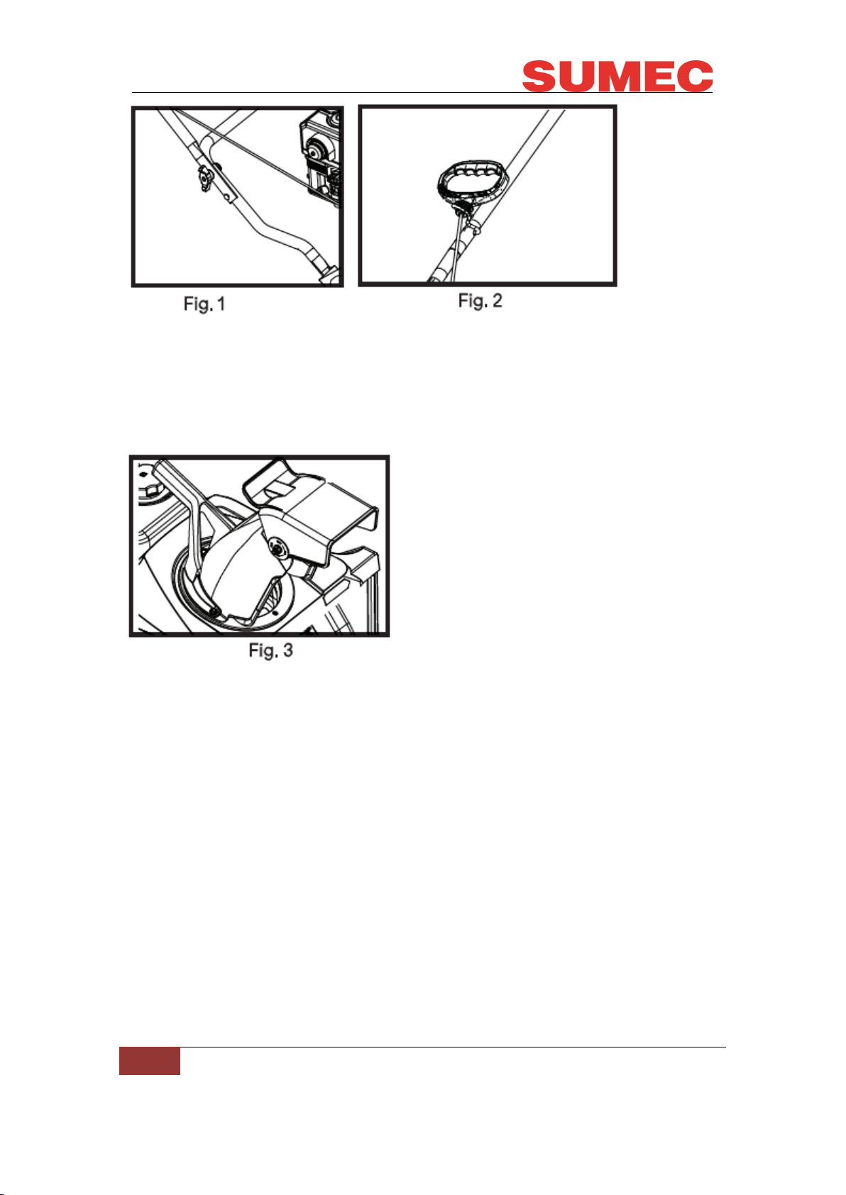
3. Install the handle knobs on the bolts (Fig. 1) and tighten the knobs securely.
4. Install and adjust the control cable (see Adjusting the Control Cable on
pg.6).
IMPORTANT: Ensure that the cable is routed on the innerside of the handle.
INSTALLING THE RECOIL STARTER HANDLE
Install the recoil starter handle in the rope guide as shown in Fig. 2.

6
INSTALLING THE DISCHARGE CHUTE
Install the discharge chute assembly as shown in Fig. 3.
Make sure the discharge chute rotation handle and discharge chute is in the
correct position, tighten 3 screws with the cross-head screwdriver.
ADJUSTING THE CONTROL CABLE
Checking the Control Cable
Before each use, check the control cable and adjust it if necessary.
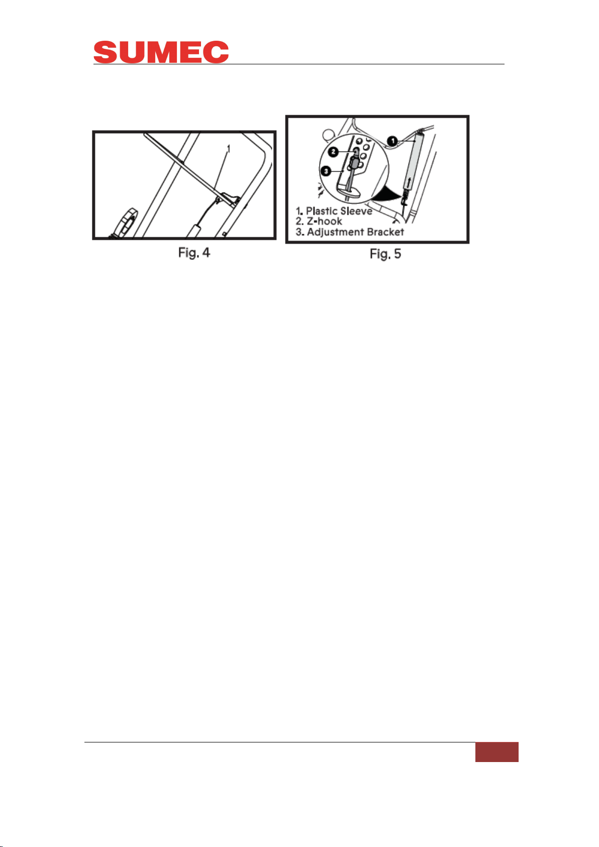
ADJUSTING THE CONTROL CABLE FIGS. 4/S
1. Stop engine and wait for all moving parts to stop and for hot parts to cool.
2. Move plastic sleeve up to auger control lever.
3. Remove cable end from adjustment bracket.
4. Insert Z-hook into highest adjustment bracket hole reachable.
5. Feed cable end through the adjustment bracket.
IMPORTANT: When auger control lever is disengaged, there should be slight
slack in the cable and no tension.
6. Start engine and engage auger control lever to ensure proper operation.
7. Release auger control lever and ensure paddle rotation stops.

7
IMPORTANT: Cable tension should not be excessive.
8. Reposition sleeve over adjustment bracket.
CHECKING AND FILLING ENGINE OIL
CAUTION! The following procedures and adjustments must be performed
before the engine is started. Do not attempt to make any of these adjustments
while the engine is running.
CAUTION! To prevent engine damage, the engine is shipped without oil or
gas.
The engine must be filled with the correct grade of oil and gas before starting
the engine.
NOTE! Running the engine with a low oil level will cause engine damage. It is
recommend that high detergent, premium quality 4-stroke engine oil be used.
Using non-detergent oil can shorten the engine's service life, and using
2-stroke oil will damage the engine.
CAUTION! Always use high quality detergent oil classified SAE 5W-30 oil or
equivalent. Never use additives with recommended oil. To prolong the life of
the engine, it is important that the oil is changed after the first 5 hours of use.
NOTE! To check the engine oil level, stop engine and place the snowblower on
a level surface.
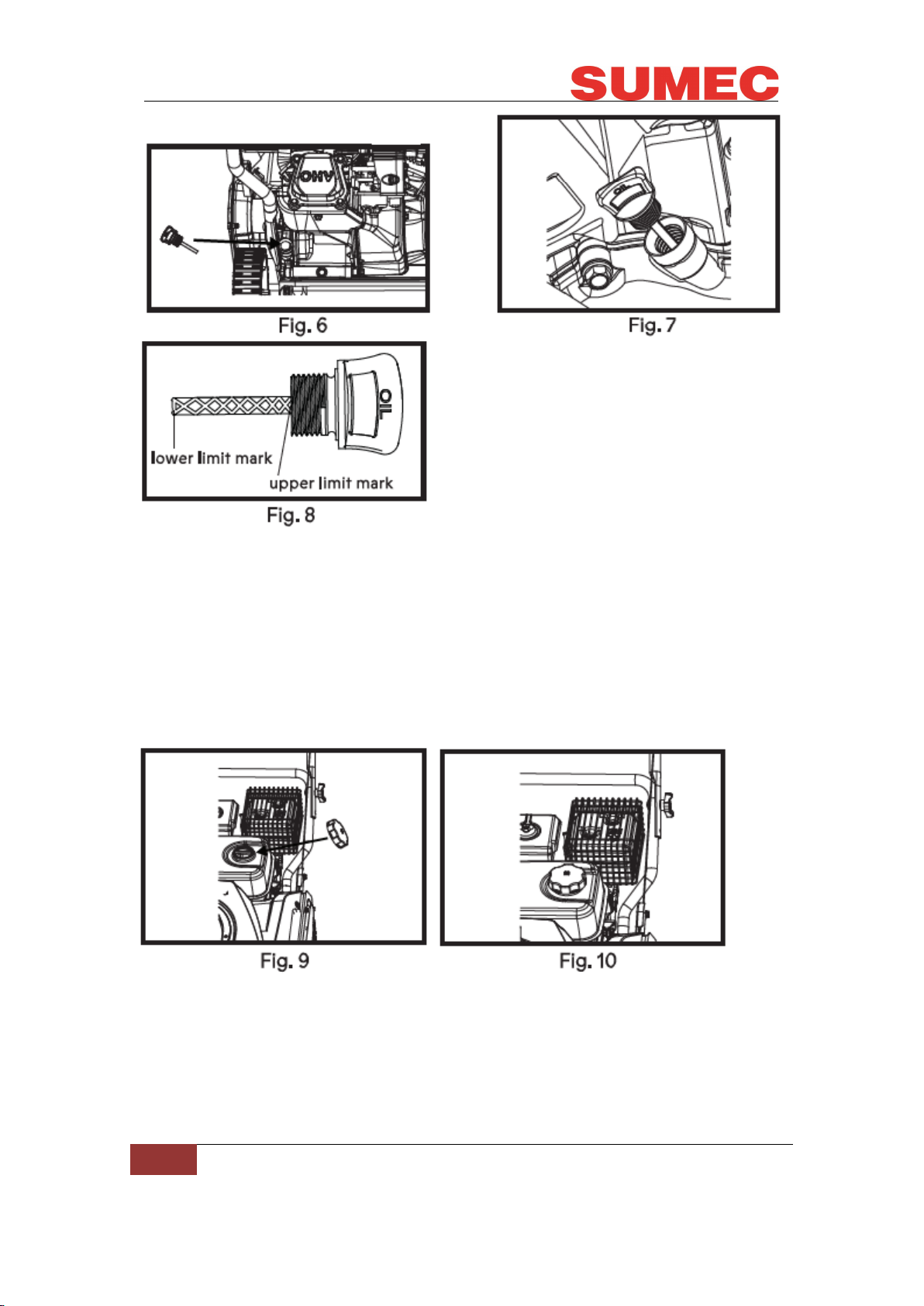
1. Remove the oil tiller dipstick and wipe oil from it with a clean cloth (Fig. 6).
2. Insert the dipstick into the oil tiller neck, twist to close (Fig. 7).
3. Remove the dipstick again and check the oil level: the oil level must be
between the lower limit mark and upper limit mark on the dipstick. The
recommended oil (SAE 5W-30 or equivalent). Do not overfill. Wipe away any
spilled oil (Fig. 8).

8
FILLING WITH ENGINE FUEL
1. Clean the area around the gas filler cap before removing the cap. Remove
the warning tag, and check the fuel level (Fig.9).
2. Refill the tank if the fuel level is low.
3. Refuel carefully to avoid overfilling or spilling fuel. There should be no fuel in
the filler neck.
4. Clean up any overflow or splashes of gas before starting the engine.
5. Tighten the filler cap after filling: finger tight only (Fig.10).
OPERATION
STARTING AND STOPPING THE ENGINE
The density of air at high altitude is lower than at sea level. Engine power is
reduced as the air mass and air-fuel ratio decrease. Engine power will be
reduced for every 3000'/914 m of elevation above sea level. This is a natural

9
trend and cannot be changed by adjusting the engine. At high altitudes
increased exhaust emissions can also result due to the increased enrichment
of the air-fuel ratio. Other high altitude issues can include hard starting,
increased fuel consumption and spark plug fouling. To alleviate high altitude
issues other than the natural power loss, we can provide a high altitude
carburetor main jet at an additional cost.
TO START THE ENGINE
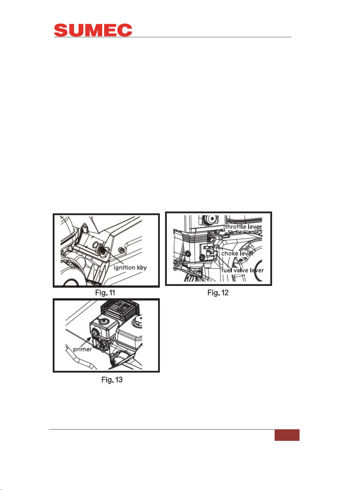
1. Push the ignition key fully inward (Fig. 11).
2. Move the fuel valve lever to the "ON" position (Fig. 12).
To start a cold engine, move the choke lever to the choke closed position
(Fig.13).
3. Move choke lever depending "ON" unit's temperature:
To start a cold engine, move the choke lever to the choke closed position
(Fig.12).
To start a warm engine, leave the choke lever to the opened position (Fig. 13).
4. Move the throttle lever to full speed to start the engine (Fig. 13).
5. Use primer control depending on unit's temperature (Fig. 13):
To start a cold engine, prime 3-5 times (Fig. 13).
To start a warm engine, do not prime.
NOTE: Do not use the primer or the choke if the engine has been running and
is hot. Excessive priming may flood the engine and prevent it from starting.

10
ELECTRIC START
NOTE: Use only a UL-Listed, 16-gauge extension cord recommended for
outdoor use that is not longer than 50 '/15m.
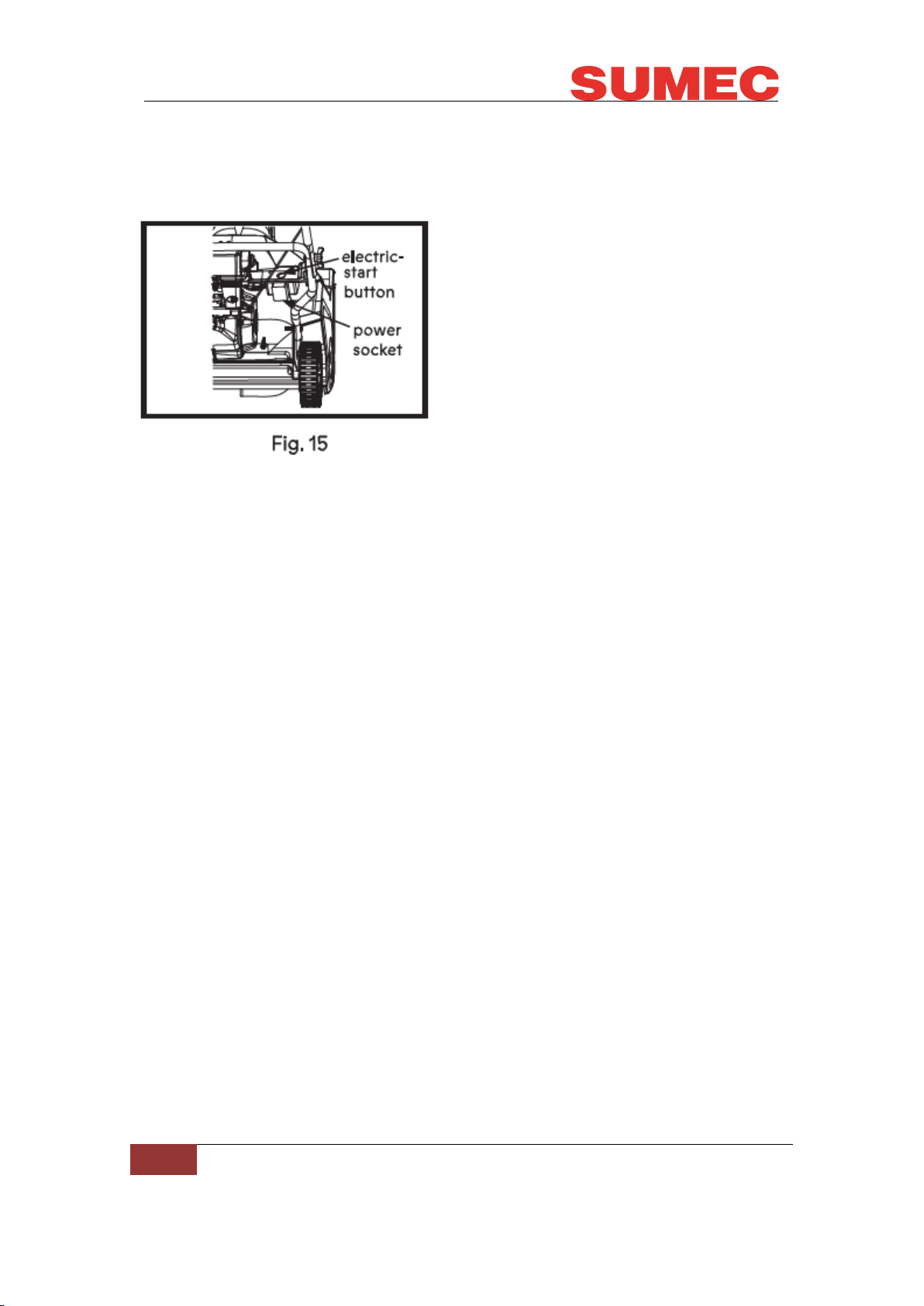
Connect an extension cord first to a power source and then to the power
socket of the machine, and press the electric-start button (Fig.15).
IMPORTANT: To prevent damaging the electric starter. Do not run the electric
starter more than 10 times at intervals of 5 seconds on, then 5 seconds off. If
the engine does not start after this series of attempts, allow the starter to cool
for at least 40 minutes before attempting to start it again. If the engine still does
not start after the second series of attempts, take the machine to an Authorized
Service Dealer for service. Once started, disconnect the plug from the power
supply and the starter.
RECOIL START
NOTE: If the recoil starter does not operate properly, it may be frozen. Thaw
out the starter before attempting to start the machine.
NOTE: If the engine fails to start after three pulls, repeat the process.
1. Pull the recoil start handle out approximately 4" to 6"/10 to 15 cm until you
feel a resistance and then start the engine with a sharp pull (Fig. 16)
2. Once the engine is running, put the starter rope into the rope guide (Fig. 16).
While the engine is running, move the choke lever gradually to the "RUN"
position;
STOP THE ENGINE
To stop the engine, pull the ignition key outward.
ENGAGING THE AUGER PADDLE
To engage the auger paddle, hold the auger control lever against the handle
(Fig. 17).
Questo manuale è adatto per i seguenti modelli
1
Indice
Altri manuali Sumec Spazzaneve