Svan SVCC1660B Manuale utente

SVCC1660B
SVCC1660N
SVCC1960B
SVCC1960N
Read this manual carefully and keep it for future reference.
USER MANUAL
COOKER HOOD

RECOMMENDATIONS AND SUGGESTIONS
The instructions for Use apply to several versions of this appliance. Accordingly, you
may find descriptions of individual features that do not apply to your specific appliance.
INSTALLATION
The manufacturer will not be held liable for any damages resulting from incorrect or
improper installation.
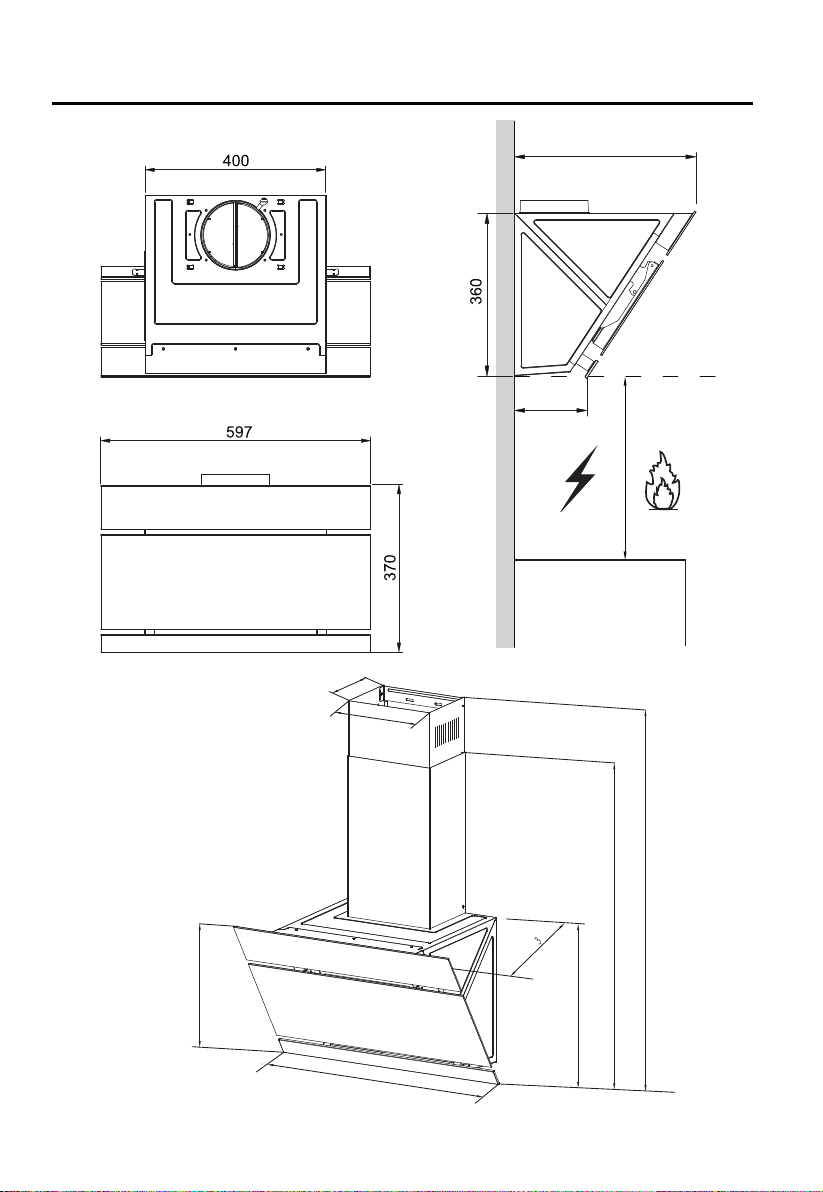
The minimum safety distance between the cooker top and the extractor hood is 650
mm (some models can be installed at a lower height, please refer to the paragraphs
on working dimensions and installation).
Check that the mains voltage corresponds to that indicated on the rating plate fixed to
the inside of the hood.
For Class I appliances, check that the domestic power supply guarantees adequate
earthing.
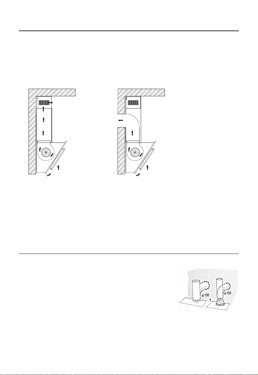
Connect the extractor to the exhaust flue through a pipe of minimum diameter 120mm.
The route of the flue must be as short as possible.
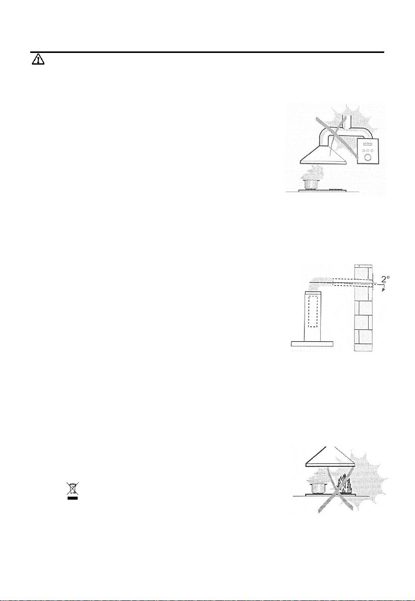
Do not connect the extractor hood to exhaust ducts carrying combustion flumes
(boilers, fireplaces, etc.).
If the extractor is used in conjunction with non-electrical appliances (e.g. gas burning
appliances),a sufficient degree of aeration must be guaranteed in the room in order to
prevent the backflow of exhaust gas. The kitchen must have an opening
communicating directly with the open air in order to guarantee the entry of clean air.
When the cooker hood is used in conjunction with appliances supplied with energy
other than electric, the negative pressure in the room must not exceed 0,04 mbar to
prevent fumes being drawn back into the room by the cooker hood.
In the event of damage to the power cable, it must be replaced by the manufacturer or
by the technical service department, in order to prevent any risks.
If the instructions for installation for the gas hob specify a greater distance specified
above, this has to be taken into account. Regulations concerning the discharge of air
have to be fulfilled.
USE
The extractor hood has been designed exclusively for domestic use to eliminate
kitchen smells.
Never use the hood for purposes other than for which it has been designed.
Never leave high naked flames under the hood when it is in operation.
Adjust the flame intensity to direct it onto the bottom of the pan only, making sure that
it does not engulf the sides.
Deep fat fryers must be continuously monitored during use: overheated oil can burst
into flames.
Do not flame under the range hood; risk of fire.
This appliance can be used by children aged from 8 years and above and persons
with reduced physical, sensory or mental capabilities or lack of experience and
knowledge if they have been given supervision or instruction concerning use of the
appliance in a safe way and understand the hazards involved.
Children should be supervised to ensure that they do not play with the appliance.
Cleaning and user maintenance shall not be made by children without supervision.
“CAUTION: Accessible parts may become hot when used with cooking appliances”.
MAINTENANCE
Switch off or unplug the appliance from the mains supply before carrying out any
maintenance work.
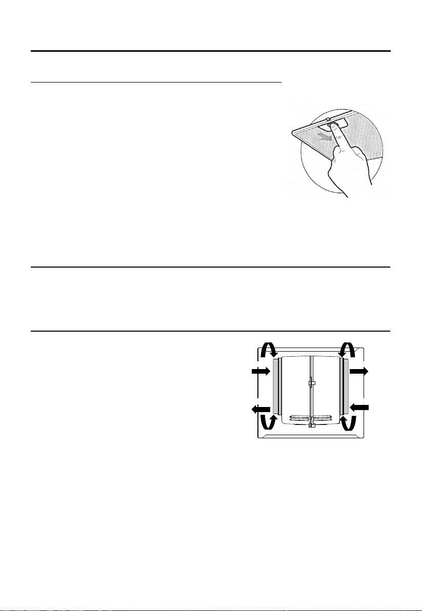
Clean and/or replace the Filters after the specified lime period (Fire hazard).
Clean the hood using a damp cloth and a neutral liquid detergent.
The appliance uses 4 hob elements at most.
The symbol is packaging indicates that this product may not be treated as household
waste. Instead it shall be handed over to the applicable collection point for the recycling of
electrical and electronic equipment. By ensuring this product is disposed of correctly, you
will help prevent potential negative consequences for the environment and human health,
which could otherwise be caused by inappropriate waste handling of this product. For more
detailed information about recycling of this product, please contact your local city office,
your household waste disposal service or the shop where you purchased the product.
EN-2

COMPONENTS
Ref.
Qty.
Product Components
1
1
Hood Body, complete with: Controls, Light,
Blower, Filter.
2.1
1
Lower Decorative Chimney(optional )
2.2
1
Upper Decorative Chimney(optional )
3
1
Flange(optional)
4
1
ExhaustPipe
5
2
The Activated Charcoal filter( optional )
Ref.
Qty.
InstallationComponents
10
7
Screws5x 50
11
7
WallPlugs
12 6 Screws 4.2 x 9.5
13 2 Mounting Bracket
20 1 Hood fixing bracket ( optional )
21 1 Chimney fixing bracket (0/1 optional )
20 11
1
12
21 10
13
Qty. Documentation
Instruction Manual
1
21 11
12
2.2 4
10
20 3
2.1
11
5
10
13
12
EN-3

DIMENSIONS
162
370
360
760
MIN 760 - MAX 1050
225
597/897
170
40
530mm
Min. 530mm
Min.
403
EN-4
/897

INSTALLATION
WALL DRILLING AND BRACKET FIXING
As a first step, proceed with the following drawings:
A vertical line up to the ceiling or up to the upper limit, at the center of the area in which the
hood is to be fitted.
A horizontal line Aat 1270 –1560 mm above the cooker top.
A horizontal line Bat a minimum 887 (840 optional) mm above the cooker top.
A horizontal line Cat a minimum 717 mm above the cooker top.
Mark Points:
Mark a point (1) on the horizontal line A, 40 mm to the right of the vertical reference line.
Repeat this operation on the other side, checking that the two marks are leveled.
Mark a point (2) on the horizontal line B, 80 (135 optional) mm to the right of the vertical reference
line.
Repeat this operation on the other side and on the vertical reference line, checking that the
three marks are leveled.
4021
A(1) 11
4012
80 80
B(2) 10
B (OPTIONAL) 20
135 135
C(3) 11
112.5 112.5
10 Oponal
11
10
1270 - 1560
887
530
717
840
EN-5

Mark a point (3) on the horizontal line C, 112.5 mm to the right of the vertical
reference line.
Repeat this operation on the other side, checking that the twomarks are on the same horizontal
line.
Fix the brackets (Optional):
Drill at the marked points (1) (2) (3), using a ɸ10 mm drill bit.
Insert the Wall Plugs 11 into the holes (1) (2) (3).
Fix the hood fixing bracket 20 with 3 screws 10 (5x 50) supplied with the hood.
Fix a Chimney fixing bracket 21 with 2 screws 10 (5x 50) supplied with the hood.
Hook the hood body:
Open the panel.
Remove the Metal grease filter using the handles provided.
Hook the hood body to the bracket 20.
Level the hood body itself.
From the inside of the hood body, fix the screws 10 to Wall Plugs 11 at the points (3).
Fit the filter into the hood.
Close the panel.
Right Wrong
EN-6

CONNECTIONS
DUCTED VERSION AIR EXHAUST SYSTEM
When installing the ducted version, connect the hood to the chimney
using either a flexible or rigid pipe ɸ150 or ɸ120 mm, the choice of
which is left to the installer.
To install a ɸ120 mm air exhaust connection, insert the reducer
flange 3on the hood body outlet.
Fix the pipe 4in position using sufficient pipe clamps (not
supplied).
Remove possible charcoal filters.
CHOOSE A VENTING MODE
Here two venting modes, extraction-air mode and recirculation mode, before installing,
select one mode.
Extraction-air mode, the air is discharged out of the house by a pipe.
Recirculation mode, the air is purified and discharged into the house through two rows of
holes on the adjustable decorative cover.
Note: For recirculation mode, no need pipe, install carbon filters.
when carbon filter attached, the suction power will be lowered.
Recirculation mode Extraction-air mode
EN-7

CHIMNEY ASSEMBLY
The chimney can only be installed with exhausting hood.
Lower Decorative Chimney
Fix a Chimney fixing bracket 21 onto the Lower Decorative Chimney with 2 screws 12
(4.2 x 9.5) supplied with the hood.
Hook the brackets 13 onto the hood body,and fix them with 2 screws 12 (4.2 x 9.5),making
sure that they are well seated.
Upper Decorative Chimney
Slightly widen the two sides of the upper chimney and hook them between the wall and the
bracket 21 which is fixed on the Lower Decorative Chimney.
Fix the upper chimney onto the bracket 21 with 2 screws 12 (4.2 x 9.5) supplied with the hood.
21
2.1
12
Slightly widen the two sides of the lower chimney and hook then between the brackets
13,fix the lower chimney onto the brackets 13 with 2 screws 12 (4.2 x 9.5) supplied with
the hood.
EN-8

USE
CONTROL PANEL
Button Function Remarks
Turns theMotor ON. When is off.
Enable shutdown the Motor with a 3 minutes
delaymeanwhile flashes. When is on.
Turns theMotor OFF. When is flashing.
Turns theMotor on atspeedLow. Buttons + are on.
Turns theMotor on atspeedMedium. Buttons + are on.
Turns theMotor on atspeedHigh. Buttons + are on.
Turns the Lighting System on and off at
maximumintensity. Button on.
Turns theMotor on atspeedBOOST. Buttons + are on.
EN-9

MAINTENANC
GREASE FILTERS
CLEANING METAL SELF-SUPPORTING GREASE FILTERS
The filters must be cleaned every 2 months of operation, or
more frequently for particularly heavy usage, and can be
washed in a dishwasher.
Pull the comfort panels to open them.
Remove the filters one by one pushing them towards the back
side of the hood unit and simultaneously pulling downwards.
Any kind of bending of the filters has to be avoided when
washing them. Before fitting them again into the hood make sure
that they are completely dry. (The color of the filter surface may
change throughout the time but this has no influence to the filter
efficiency).
When fitting the filters into the hood pay attention that they are
mounted in correct position the handle facing outwards.
Close the comfort panel.
ACTIVATED CHARCOAL FILTER (RECIRCULATION VERSION)
These filters are not washable and cannot be regenerated, and must be replaced approximately
every 4 months of operation, or more frequently with heavy usage.
REPLACING THE ACTIVATED CHARCOAL FILTER
Open the comfort panels pulling them downwards.
Remove the metal grease filters
Remove the saturated activated charcoal filter.
Fit the new filters.
Replace the metal grease filters.
Close the comfort panel
FIX REMOVE
FIX
REMOVE
EN-10
Questo manuale è adatto per i seguenti modelli
3
Indice
Lingue:
Altri manuali Svan Cappa di ventilazione

Svan
Svan SCPD600AN Manuale utente

Svan
Svan SVCC8080B Manuale utente

Svan
Svan SCPT600A1IX Manuale utente

Svan
Svan FREE FLOW Manuale utente

Svan
Svan SCPP600BX Manuale utente

Svan
Svan SVCE553G Manuale utente

Svan
Svan SVCC9070 Manuale utente

Svan
Svan SCPE601CX Manuale utente

Svan
Svan SVCC9074B Manuale utente

Svan
Svan SVCT900 Manuale utente


