SynthCube Eurorack Version Manuale

Synthcube DIY Eurorack Modular sMs Audio Electronics Doc. Rev “A”
PAGE 1
“Thomas Henry Super Controller Module”
Eurorack Version
Build and Test Manual Doc. Rev. A

Synthcube DIY Eurorack Modular sMs Audio Electronics Doc. Rev “A”
PAGE 2
Table of Contents:
SCM Overall Description ……………………………………………………………………… 3
Functional Description ………………………………………………………………………… 4
Build Notes …………………………………………………………………………………………. 7
Parts Checklist ……………………………………………………………………………………. 10
Resistor Placements …………………………………………………………………………… 12
Capacitor Placements …………………………………………………………………………. 35
Integrated Circuit Placements …………………………………………………………….. 48
Transistor & Switching Diode Placements …………………………………………… 50
J1/J13 Power Connector Placements ………………………………………………….. 51
Jack Placements ………………………………………………………………………………….. 52
Switch Placements ………………………………………………………………………………. 54
Potentiometer Placements ………………………………………………………………….. 55
PCB Board Views (Front and Rear) ……………………………………………………….. 56
LED Placements ……………………………………………………………………………………. 58
Knob Placements ………………………………………………………………………………….. 59
Power ON first time ……………………………………………………………………………… 61
Setting up The SCM ……………………………………………………………………………… 62
Bill of Materials (Detailed with MFG Part Numbers) ……………………………. 69
Schematic Diagram ……………………………………………………………………………… 69

Synthcube DIY Eurorack Modular sMs Audio Electronics Doc. Rev “A”
PAGE 3
SCM Overall Description:
This module & SMT PCB was designed and manufactured with kind permission of
“FONITRONIK” and Thomas Henry. It is the Supercontroller Circuit published in
Polyphony Issue Sept./Oct. 1981 and his book “Build a better music Synthesizer”
1987. This version of the module is a Eurorack format with some extra
functionality added such as an extra delay mode and external sample & hold
clock. To quote Thomas Henry: “If the VCO, VCF, and VCA form the heart of a
synthesizer, then this module is surely the brain! It gives you most standard
controller options (LFO, noise source, and sample and hold), but also includes
some extras. The heart of the Super Controller Module (SCM) is the SN76477. This
chip is known as a complex sound generator and was originally designed to
provide sound effects for pinball machines and other computer type games.”
Another use of the SN76477 chip is in the famous video game from 1978 called
Space Invaders. The chips role in the Space Invaders game was to meerly produce
the flying saucer sound thus it was hardwired for this single sound on the games
sound board. Other sound generating circuits on the sound board filled the roles
of all the other sounds for the game. Seems a waste and Thomas Henry certainly
recognized all the chips possibilities many years ago. A great companion to the
Thomas Henry SCM is the SN Voice Module shown below of which is also a
Eurorack version available at Synthcube.
Eurorack Thomas Henry SN Voice
Functional description:

Synthcube DIY Eurorack Modular sMs Audio Electronics Doc. Rev “A”
PAGE 4
Figure 1 SCM functional sections
The picture above in figure 1 shows the front panel of Euro module. Each section
is color coded for easy identification for this discussion.
The LFO section located in top left: You can choose three modes of operation with
the three position switch which are two delay modes and a gated mode. In the
INV delay mode, switch in the middle position, the LFO turns off when triggered
and after a certain amount of time, depending on the LENGTH knob setting, will
turn back on . In the TRIG delay mode , switch in the left position, the LFO will be
off and then and turn on immediately when triggered, stay active for a delay time
depending on the LENGTH setting, will turn back off. It should be noted that
turning the LENGTH knob CW increases delay and CCW decreases the delay time.
In GATE mode, switch in the right position, the LFO is always “on” until you plug a

Synthcube DIY Eurorack Modular sMs Audio Electronics Doc. Rev “A”
PAGE 5
cable into the GATE jack. From now on the LFO is only “on” when a gate signal is
present. The status LED on the right indicates the LFO on-off-status. There is a
selector for the LFO range of which there are three (LO, MID, HI), and a RATE
control with a sub-hertz to approximately 350 Hz. The LED on the left flashes at
the rate the LFO.
There are four OUTPUTS in the lower left: TRIANGLE, SQUARE, GATE, and
TRIGGER that are all derived from the LFO. The 0V to approx 10V GATE output is
derived from the square wave output. The TRIGGER is derived from the triangle
and delivers a positive 1ms pulse. Don't forget: The outputs are gateable by the
DELAY and GATE modes in the LFO section. The SQUARE and TRIANGLE are both
bi-polar signals and can be used as audio sources also.
The S/H section: The S/H in the bottom right, the CLK input is internally normalled
to the LFO trigger. With a clock jacked into CLK, a slow rising clock as low as 1.2 V
peak can clock the S&H this it works equally as well with fast rising pulses or slow
sine waves and ramps. The image below in figure 2 illustraites the action of a sine
wave clock on trace one with a peak amplitude of 1.16 volts. Trace two is the
input and trace three is the resultant sampled waveform. In this example, the lag
is set to minimum and the depth is set to maximum amplitude.

Synthcube DIY Eurorack Modular sMs Audio Electronics Doc. Rev “A”
PAGE 6
Figure 2 External Sample Clock Example
The S&H provides a portamento (lag) and depth control. The input “IN” is
normalled to the SCM’s NOISE source with the ability to accept a bi-polar input
source.
The NOISE section to the top right: the frequency range of the noise source is
selectable by a switch (LO, MID, HI). Thomas Henry: ”Something should be said
about why you might want to change the clock rate. The best answer is, try it,
you’ll like it! The sound is an incredible swooshing noise not unlike phasing or
flanging. The noise takes on a new tonality and sweeping the clock changes the
spectra in a dramatic and eerie manner.”Furthermore there is a filter control
(known from the SN voice) and a attenuated CV in for the sweep, which base
frequency is set by the FREQ control. you can select external (EXT) modulation
(switch left) or internal (LFO) sweep modulation (switch right)

Synthcube DIY Eurorack Modular sMs Audio Electronics Doc. Rev “A”
PAGE 7
Building the SCM:
If you are building this board its likley you have constructed boards using SMT
devices but for folks that are just beginning their journey, here is a useful video to
check out:
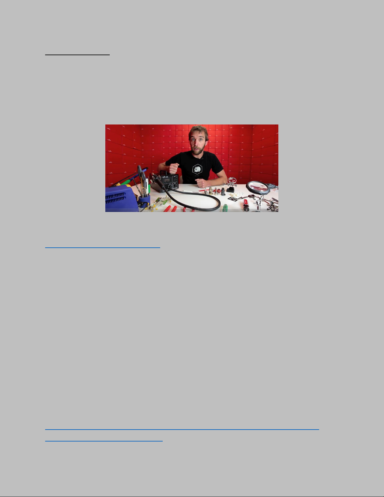
SparkFun Hot Air Rework tutorial with David Stillman Time: 4:36 :
Photo 1 David Stillman
https://youtu.be/9D0oTGeheBA
There are thouands of video tutorials about SMD soldering on Youtube that you
can watch. Some better than others so watch several. Remember, you’re not
limited to using a hot air rework station. It is just my preference. Because of the
size of the components chosen for the the SCM PC board, you can also get away
with using a soldering iron with a fine tip and steady hand to solder all the
components. This was an important design goal of this PCB.
The hot air rework station that I personally use is the YiHUA Model 898D shown in
photo 2 and find its quality and price are excellent and perfect for all hobby
soldering jobs. The model 898D goes by several other names so just plug in a
search for the 898D hot air rework. Amazon has the best deals. The link is shown
below. The price range at the time of writing manual ranges from about $50.00 to
$65.00 USD which is quite an excellent deal.
https://www.amazon.com/s/ref=nb_sb_noss?url=search-alias%3Daps&field-
keywords=898D+hot+air+rework

Synthcube DIY Eurorack Modular sMs Audio Electronics Doc. Rev “A”
PAGE 8
Photo 2 Hot Air Rework Station
Other essential items you will need are shown below in photo 3 and 4. I use
solder paste that is leaded and find it easier to work with. I use acid brushes
instead of a toothbrush. I also use lead/tin solder paste & solder. I like to use a
manual paste dispenser like the one in photo 3.
Photo 3 Manual Solder Paste Dispenser

Synthcube DIY Eurorack Modular sMs Audio Electronics Doc. Rev “A”
PAGE 9
Photo 4 Suggested Tools for Soldering
To prepare the board, clean with alcohol or flux remover then use an air duster to
dry and blow any remaining debre off the board.
I also find these tools essential, magnifier with light and heat mat:
HEAT MAT
Locate and identify that you have all you components. Use the check boxes as
you go.

Synthcube DIY Eurorack Modular sMs Audio Electronics Doc. Rev “A”
PAGE 10
RESISTORS:
QTY REFERENCE VALUE CHECK
17
R1,R7,R9,R11,R13-R14,R23,R30-R31 ,R33,R40,R44-
R45,R50,R53-R54,R61
100K
__________
2
R2,R20
1.0M
__________
4
R3-R4,R22,R24
3K
__________
4
R5,R21,R32,R49
1.00K
__________
3
R6,R26,R42
2.2M
__________
8
R8,R12,R25,R41,R38,R43,R56-R57
10K
__________
3
R10,R15,R27
2.20K
__________
2
R16
390K
__________
1
R51 (SEE NOTE 1)
249K
__________
1
R17
15.0K
__________
1
R18
68K
__________
1
R19
5.6M
__________
2
R28,R39
220
__________
1
R29
10
__________
4
R34,R58-R59,R62
33K
__________
1
R35
4.7K
__________
3
R36,R46-R47
47K
__________
1
R37
39K
__________
1
R48
200K
__________
1
R52
22K
__________
1
R55
220K
__________
1
R60
56K
__________
NOTE 1 : IF POWERING THE MODULE FROM J13 MOTM (+15, -15 VDC) then R51
is 390K, same part type as R16.
Indice