Takex ASW-SG85F Manuale utente

COMPONENTS1CONNECTIONS4
SAFETYCAUTIONS2
OPERATINGCAUTIONS3
Wafermappingsensor
●Input/outputcircuit
Capacitorground
DC12〜24V
DC5V
Lightemissioninhibitinput
Outputinhibitinput
CHanderroroutputs
0V
※Foranoiseprevention,acapacitorisinstalledbetween
the0Vpowersupplyandthesensor'saluminumcase.
1/4
Internalcircuit
Thefollowingcautionsmustbestrictlyobservedinordertoensuresafety.
1.Thisproductisnotdesignedfortheuseinsafetysystemswhichdetectthe
presenceofhumanbody.Donotusethisproducteitherdirectlyorindirectly
forapplications.
2.Donotusethisproductwhenitscaseorcableisinadamagedcondition.
3.Donotattempttodisassemble,repair,ormodifythisproduct.
4.Donotusethisproductinenvironmentswhereflammable,explosive,or
corrosivegasesarepresent.
5.Donotusethisproductinenvironmentswheretheproductcouldbeexposed
tooilsandchemicals.
6.Donotusethisproductinwater,inrain,oroutdoors.
7.Donotusethisproductunderconditionsorinenvironmentswhichexceed
theproductratings.
8.Donotusethisproductinlocationswhichareexposedtodirectsunlight.
9.Donotusethisproductinlocationswhichreceivedirectvibrationsorimpact
shocks.
10.Donotwipethisproductwiththinner,alcohol,oranyotherorganicsolvent.
11.Performdailyinspectionsandperiodicinspections(approximatelyeveryweek)
togetherwiththeprescribedmaintenance/inspectionprocedurestoverify
thattheproductisfunctioningnormally.
12.Thisproductmustbediscardedofasindustrialwaste.
(refertodimensionsforshapesandsizesofeachcomponent.)
TAKENAKAELECTRONIC
INDUSTRIALCO.,LTD.
Headoffice,factory
Telephone
FAX
:
20 -1
Narano -cho,Shinomiya,Yamashina -ku,
:Kyoto
607 -8032
,Japan
:
+81
-
75
-
581
-
7111
:
+81
-
75
-
581
-
7118
InstructionManual
1.Placinghigh-voltagecables,powercables,andtheproductwiringtogetherina
singleconduitorductcouldcauseinduction-relatedmalfunctionsandpossible
equipmentdamage.Makesuretoseparatethesecableswhenwiring.
2.Avoidapplyinganexcessiveforcetothecables.
3.
AlwaysinstallanFG(framegroundterminal)whenusingacommerciallyavailable
switchingregulator.
4.Becausedetectionisenabled1secaftertheproduct'spoweristurnedON,
alwayswait1secafterpowerONbeforeattemptingtotheusetheproduct.
Iftheloadandtheproductareconnectedtodifferentpowersupplies,besure
toturntheproduct'spowerONfirst.
5.BecauseanoutputpulsemaybegeneratedatpowerOFF,werecommendthat
theloadortheloadline'spowerbeturnedOFFfirst.
6.DonotuseinapplicationswherethepoweristurnedONandOFFina
continuousmanner.
7.Fortheoperationpowersupply,limitthecurrent(2A)inaccordancewiththe
conductorsizewhichisconnectedtotheconnector.
8.Screwsshouldnotbescrewed-in8mmormoreintothesensorwhenmounting.
Chooseaproperlengthofscrewsaccordingtothethicknessofthefixingbody.
Thesensormaybedamagedifinappropriatelylongscrewsareused.
Comb
Switchcover
CH1(1stbeamaxis)mark
M4x8screw
※
ConnectorFujitsu
FCN-361J040-AU
Fixingplateforpacking
(Removebeforeusingsensor)
※(TheM4×8screwsareusedtofix
thefixingplate.Donotusethesescrews
tomounttheproduct.)
●Pinconfigurationdiagram
Eachsignalispassedfromthesensorthroughthecable,andconverted
fromserialtoparallelintheconnector.Threeconnectorpinsareused
eachforthepowercable's+24Vand0V.
toallowtheconsumptionandoutputcurrent,
connectthethreeinparallel.
Whenusingthe*1and*2lightemissioninhibitinputandoutputinhibit
input,connectthereturnwiretotheconnector's0V(B8,B13,B14).
Thetwolightemissionsinhibitinputandoutputinhibitoutputwiresare
connectedinthesensor.
AFujitsuFCN-361J040-AUconnectorisused.
Confirmthattheconnectoriscorrectlyconnectedbeforeturningthe
powerON.
Donotusednon-specifiedpinnumbersforjunctionwiring,etc.
+24V
+24V
+24V
0V
0V
0V
*1
*1
*2
*2
CH1
CH2
CH3
Ch4
Ch5
Ch6
Ch7
CH8
CH9
CH10
CH11
CH12
CH13
Ch14
CH15
CH16
Ch17
CH18
CH19
CH20
CH21
CH22
CH23
CH24
CH25
CH26*4
B7
B10
B11
B8
B13
B14
B16
B17
B19
B20
A1
A2
A3
A4
A5
A6
A7
A8
A9
A10
A11
A12
A13
A14
A15
A16
A17
A18
A19
A20
B1
B2
B3
B4
B5
B6
B9
Sensor Name Connectornumber
*3
* 1:Lightemissioninhibitinput
* 2:Outputinhibitinput
*3:Erroroutput
* 4:ASW-SG86F
Externalwiringandconnectornumber
ASW -SG85F/ASW -SG86F
Internalcircuit

OPERATION5
SETTING6
2/4
・Left-sidesetting:Standardoperationmode(defaultsetting)
・Right-sidesetting:Automaticsensitivityadjustmentmode
●
Preparation
Firmlysecurethewiringconnectorsasdescribedinsection4
"Connections".BeforeturningthepowerON,removetheswitch
coverandmaketheappropriateswitchselections(seesection6(1)
"Switches").
*Afterchangingtheswitchsettings,besuretoturnthepower
OFFandbackON.
(1)TurnthepowerON.
*BeforeturningthepowerON,checkagaintoverifythatthe
connectionsarecorrect.
Usecarebecausetheoutputsarenotequippedwithshort-circuit
protectioncircuits.
(2)TheTEACHmodeisestablishedwhenthepoweristurnedON.
*WhenintheTEACHmode,verifythatnothingisblockingthelight
beam.
(3)Performstandardoperation(seesection6(2)"Functions").
*Becausetheproducthasbeenadjustedtodetectwaferswhich
arenearlytransparent,anfalseoutputcouldoccuriftheproduct
issubjectedtoanimpactshockorvibrationwhilethesensoris
movingorstationary.
Moreover,amalfunctioncouldoccurifthecomb'stipistouched
bythewafer,orbyafinger.
Ifthecombistouchedinthismanner,theTEACHoperationmust
berepeated(seesection6(2)"Functions").
*Ifthecombbecomesdamaged,replaceitasdescribedinsection
8"MaintenanceandInspection".
(1)Switches(seeFig.1)
Openthesensor'sswitchcover,thenspecifythedesiredoperation
modebysettingthetwoswitches.
●
SwitchA(outputoperationsetting)specifiesthesensor
outputoperation.
・Normaloutputmode:settheswitchtotheleft.
(OutputON/OFFoccursaccordingtoobjectpresence/absence.
Thisisthedefaultsetting.)
・Latchoutputmode:settheswitchtotheright
(OncetheoutputswitchesON,thisONstatusismaintained.)
*Thelatchoutputmode(sensoroutputONHOLD)canbe
canceledbyexecutingtheLightemissioninhibitsignal.
●
SwitchB(automaticsensitivityadjustmentsetting)is
usedforsensorsensitivityadjustments.
Thisadjustmentoperationautomaticallyadjuststhesensitivityof
eachopticalaxischannelindividuallyandisrequiredonlyaftera
combhasbeenreplaced.
Besuretoperformtheadjustmentafterreplacingacombwhichhas
becomedamaged,etc.
SettheswitchBtoautomaticsensitivityadjustmentmodeandturn
thepowerON.
Besurethatnothingisblockingthelightduringtheautomatic
sensitivityadjustmentoperation(lightreceptionisrequiredatthis
time).
Followingtheautomaticsensitivityadjustmentoperation,besureto
returntheswitchsettingtothestandardoperationsuretoreturn
theswitchsettingtothestandardoperation
SwitchA:Outputoperationsetting
Normaloutputmode←→Latchoutputmode
SwitchB:Automaticsensitivityadjustmentsetting
Standardoperationmode←→Automaticsensitivityadjustment
(2)Functions
●
PowerONandTEACHoperation
WhenpoweristurnedONinthestandardoperationmode,the
internalcircuit'soperationischecked,andaninitialTEACH
operationoccurs.
BesurethatnothingisblockingthelightatpowerON.
Ifteachingcannotbeperformedforsomereason(lightisblocked,
combismissingordamaged,etc.),theerroroutputturnsON,and
theerrorchannel'soutputturnsON/OFFrepeatedly.
●
Outputinhibitinput
Turnseachchannel'sopencollectoroutputOFFregardlessofthe
sensoroperationstatus.
Thisfunctioncanbeusedwhentheoutputsofmultiplesensors
areconnectedinparalleltoaPLC.
Thisfunctioninhibitstheoutputsofunnecessarysensorswhichis
areconnectedtothePLC.
●
Lightemissioninhibitinput
WhenthisinputisturnedON,a"lightblocked"and"outputON"
statusoccursatallchannels.
WhenthisinputisturnedOFF,are-teachingoperationoccurs.
Performthisre-teachingoperationwhilethesensorremains
stationary.
Donotperformare-teachingoperationwhilethesensorisinmotion.
There-teachingoperationiscompletedwithinapproximately1sec
afterthelightemissioninhibitinputisturnedOFF.
After1secelapses,performamotionoperation.
Toobtainoptimaldetection,turnthelightemissioninhibitinputON
→OFFwhilethesensorisinastandbystatus(beforeproceeding
tothewaferdetectionoperation)inordertoperformre-teaching.
●
Erroroutput
AnerroroutputisissuedatpowerONifanoperationalproblem
exists(abnormalchannelcondition,insufficientlightreception,
lightabnormalityduetoadamagedcomb,malfunctiondueto
ambientlightinterference,etc.).
WhentheerroroutputturnsON,theerrorchannel'soutputturns
ON/OFFrepeatedly.
SwitchA:Outputoperation,setting(factorysetting)
SwitchB:Automatic
sensitivityadjustmentsetting

3/4
●
Timechart
TeachingoccursatpowerONandatthelightemissioninhibitinput.
Ifteachingcannotbeperformedorasensormalfunctionisdetected
forsomereason,theerroroutputturnsON,andtheerrorchannel's
outputturnsON/OFFrepeatedly.
Whenusingthelightemissioninhibitinputhadbeenusedtoperform
re-teaching,there-teachingoperationisperformedafterthelight
emissioninhibitinputrecovery.Therefore,alwayswaitonesecond
orlongerbeforestartingoperation.
●
Automaticsensitivityadjustment
Thisadjustmentisusedtoadjustthecombsensitivityfollowinga
combreplacement.Besuretoperformtheautomaticsensitivity
adjustmentafterreplacingacomb.
Thisadjustmentcanbeperformedsimplybysettingtheswitchto
theautomaticsensitivityadjustmentmode,andthenturningthe
powerON.
BeforeturningthepowerON,besurethatthenothingisblocking
thelight.
AlloutputsareONduringtheautomaticsensitivityadjustment.
Theadjustmenttakesapproximately6seconds.Whencompleted,
alloutputsturnOFF,ONthenOFF,indicatingthattheadjustmentis
completed.
Ifanerrorchannelexistswhentheautomaticsensitivityadjustment
occurs,theerrorchannel'soutputturnsON/OFFrepeatedly.
Iftheadjustmentiscompletednormally,returntheswitchtothe
standardoperationmode,thenturnthepowerOFFandbackON
againbeforestartingoperation.
●
Latchoutputmode
Thismodedetectsthewaferedge,andisusedforhightransmittance
(translucent/transparent)wafers.
Aftertheedgeisdetected,theoutputONstatusismaintained.
Notethatofsomewafertypes(dependingontheedgethicknessand
shape)ismaynotbedetected.
Therefore,besuretoevaluatethewaferattributescarefullybefore
operation.
Moreover,inordertodetectthewaferedge,thewaferconveyance
speedmustbe10mm/sec.orless.
●
Resetthelatchoutput
Wheninthelatchoutputmode,thelatchONstatuscanbereset
(outputOFF)byturningthelightemissioninhibitinputtoONand
thenOFF.
MAINTENANCEANDINSPECTION8
RATINGS/PERFORMANCE/SPECIFICATIONS9
OPERATINGENVIRONMENT
Afterreplacingadamagedcomb,besuretoperformtheautomatic
sensitivityadjustment.
Seesection6-1"Switches"fortheautomaticsensitivityadjustment
procedure.
*Althoughthecombsaredetachable,usecarewhendetachingthem.
Moreover,donotinterchangethecombpositions.
ON
OFF
OFF
ON
OFF
ON
Light
received
Light
blocked
Checkthelightisblockednormally.
Re-teachingrange
Openrange
1sec
1sec
PowerON
Allchannels
output
Lightemission
inhibitinput
Output
inhibitinput
Detachingacomb Attachingacomb
①Pressthecomblockinglevers
inwardthenpullupwardto
removethecomb.
②Afterproperlyorientingthecomb,
pressitinuntilalatchingsound
(click)isheard.Thislocksthe
combinplace.
Throughbeam
24VDC±10%,ripple10%orless
1.8Worless
12msorless
InfraredLED(870nm)
Opencollectororcontactinput
OutputinhibitON:1.5Vorless;OFF:4Vorless
Attachedcablewithconnector(FujitsuFCN-361J040-AU)
Sensorunit:Polycarbonate;Housing:Aluminum
Detachabletype
8-inchwafer
(normaloutputmode:transmittanceof30%orless/
latchoutputmode:transmittanceof70%orless)
Dark-ON
Normaloutpoutmode/latchoutputmodeselectable(with
switch)ONaterroroutput
NPNopencollectoroutput
Rating:sinkcurrent30VDCorless,20mAorless
Opencollectorinputorcontactinput
LightemissioninhibitON:1.5Vorless;OFF:4Vorless
Normaloutputmode:LightemissioninhibitatON.
Re-teachingatOFF.
Latchoutputmode:Latchoutputreset,Light
emissioninhibitatON.
Re-teachingatOFF
Ambientillumination
Ambienttemperature
Ambienthumidity
Protectivestructure
Vibration
Shock
1,500 lxorless
−10〜+55℃(non-freezing)
35〜85%RH(non-condensation)
IP40
10〜55Hzdoubleamplitude0.5,X,Y,Zdirections,2hourseach
300m/s
2
X,Y,Zdirections,3timeseach
Operation
range
Operation
range
Mountinginstruction7
M4tapmountingholesareprovidedasshownbelow.
(RefertotheOutlineDimensionsfordetails.)
M4tapdepth8mm
*ReplacementsensorunitModel:ASW-F2500
Model
Numberofchannels
6.35mm
25ch 26ch
Operationmanual
ASW−SG85F
ASW−SG85F−05
ASW−SG86F
ASW−SG86F−05
Cablelength:3m Cablelength:3m
Cablelength:0.5m Cablelength:0.5m
Approx.
390g
Approx.
250g
Approx.
400g
Approx.
260g
Wafertypes
pitch
Detectionmethod
Comb
Powersupply
Currentconsumption
Operationmode
Outputmode
Responsetime
Lightsource
Outputinhibitinput
Lightemission
inhibitinput
re-teaching
Connection
Material
Weight
Accessories
※Fornoiseprevention,acapacitorisinstalledbetween
the0Vpowersupplyandthesensor'saluminumcase.

4/4
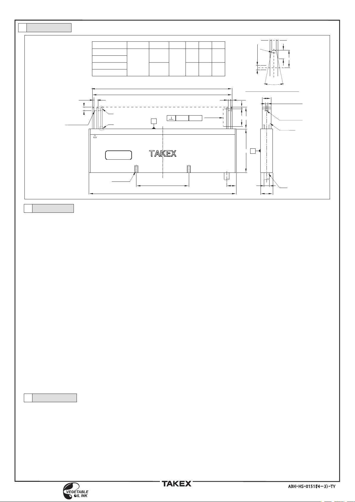
DIMENSIONS10 (Units:mm)
ABH
-
HS
-
0151(ʼ14−3)
-
TY
WARRANTY11
TakenakaElectronicIndustrialCo.,Ltd.(Takenaka)guaranteesthequalityoftheproductdescribedinthismanual,basedonTakenakaQuality
Standard.Pleasecontacttheagentorsalesofficewhereyouboughttheproductifyoufindanydefects.
1《Warrantyperiod》
Thewarrantyperiodofthisproductisoneyearaftertheinvoicedate.Thiswarrantydoesnotapplytoconsumablepartssuchasbatteriesor
relays.RegardingaproductofanothermanufacturersoldbyTakenaka,thewarrantyconformstothequalitystandardofthemanufacturer.
2《Scopeofwarranty》
Ifanydefectisfoundduringthewarrantyperiod,Takenakawillrepairorreplacetheproductwithoutcharge.
Thefollowingcasesarenotcoveredbythewarrantyevenwithinthewarrantyperiod.Pleasenotethatthewarrantyperiodisnotextendedafter
arepairorreplacement.
①Iftheproductisusedinappropriatelyorusedunderinappropriateconditionsthatarenotdescribedintheinstructionmanualorspecifications.
②Ifthedefectiscausedbyimpropermaintenance,includingafailuretoreplaceconsumableorperiodicalpartsasdescribedintheinstruction
manualorspecifications.
③Ifthedefectisnotdirectlycausedbythewarrantiedproduct.
④IftheproductismodifiedorrepairedbypersonsnotauthorizedbyTakenaka.
⑤Ifthedefectiscausedbyroughhandling,dropping,orcollisionaftertheproductisdelivered.
⑥IfthedefectcouldnotbepredictedfromatechnicalviewpointatthetimeTakenakamadetheagreementfor,manufactured,orinstalledtheproduct.
⑦Ifthedefectiscausedbyanaturaldisastersuchasafire,flood,earthquake,lightning(includingalightningsurge)andsoon,oranaccident
suchasanabnormalvoltagethatTakenakaisnotresponsiblefor.
ThewarrantyprovidedhereisonlyfortheTakenakaproductanddoesnotcoveranysecondarydamagecausedbyproblemsrelatedtotheproduct.
3《TargetofWarranty》
(1)WhencombiningtheTakenakaproductwithaproductmadebyanothermanufacturer,confirmanyrelatedlaws,rules,regulations,standards,
andsoon.Itisthecustomerʼsresponsibilitytoconfirmthesuitabilityoftheproductforthesystemordeviceitistobecombinedwith.
(2)Thisproductisdesignedandmanufacturedforindustrialuse.Thiswarrantydoesnotcovertheapplicationoftheproductto:
(1)Equipmentfornuclearfacilitiesincludingnuclearpowerstationsornuclearcontrolfacilities,incinerationsystems,railwayvehicles,aircraftor
automobilesandtheirrelatedfacilities,medicalequipment,entertainmentequipment,safetydevices,equipmentregulatedbyadministrative
bodiesorspecificindustries.
(2)Equipmentthatmaycreateseriousdangeroradverselyaffecthumanlifeorproperty.
(3)Publicutilitiesforelectricity,towngasorwatersupply,orequipmentthatrequiresconsistentreliability,suchas24-hourcontinuousoperation.
(4)Usageoutdoorsorusageinconditionsorenvironmentsthatarenotprescribedintheinstructionmanuals.
(5)Usageorequipmentthatrequiresconsiderablecareorattentiontosafety,similartothecasesin①to③.
ThiswarrantymaycovertheseapplicationsifTakenakaisnotifiedabouttheapplicationoftheproductbeforesaleandthecustomerapproves
thecompatibilityandthespecificationoftheproductbywrittenagreementand/orbyprovidingtherequiredsafetymeasures.
DISCLAIMER12
●
Thisproductisdesignedforindustrialapplicationstodetectthepresence,absence,orpassageofavarietyofobjects.Ithasnofunctionsto
preventdisasters,accidents,deathorinjuries.Takenakawillassumenoresponsibilityfordamagesorlossesresultingfromaccidentsordisasters
causedbyafailureoftheproduct,incompletewiringorinstallation,oranyactthatdoesnotfollowtheinstructionmanual.
Wewillassumenoresponsibilityfordamagesorlossescausedby:
●
Earthquakes,lightning(includinglightningsurges),firesthatwearenotresponsiblefor,actsorincidentscausedbythirdparties,intentionalor
accidentalmisuse,orusageunderotherabnormalconditions.
●
Anysecondarydamagecausedbytheusage,faultyoperation,ormalfunctionoftheproductlikesuspendedoperationormalfunctionofa
connecteddeviceorsystem,damagetoadevice,lossofprofit,interruptionofbusiness,corruptionorlossofmemorycontents,costof
restoration,etc.
●
Misuse,failurerelatedtomaintenance,installationordeinstallation,orfailuretofollowthecontentsoftheinstructionmanual.
●
Anymalfunction(includingfalsealarmorlostalarm)causedbythecombinationwithaconnecteddeviceorsoftwareoverthatwehavenocontrol.
TheresponsibilityofTakenakaislimitedtotheextentofrepairorreplacementoftheproduct.Theexpensesweareliableforwillnotexceedthe
originalproductcost.
[The dimensions shown in these drawings apply to the bottom end(※2), not the protrusion
end(※1)of the combs]
14
Ø6
0.4 0.4
1
※tail of the protrusion end of the comb
R0.6
2
(23°)
4
10
(10)
2-M4TAP×8
60
L3
20
2
W
25
50
1.8
P
4
1.8
※2
※1
1Ch
L1
P(Pitch)×N(Channel)=L2
165.1
158.75
6.35
26
25
166.9
160.55
4.55
175
168.65
ASW-SG85F
ASW-SG85F-Y05
ASW-SG86F
ASW-SG86F-Y05
P(Pitch)形式 W(Width)N(Channel) L1 L3L2
cable
sensor unit
optical axis
center position
B
0.35
A,B
A
optical axis
center position
1(optical axis width)
3(optical axis width)
1Ch
optical axis
center position
P(Pitch)×N(Channel)=L2
ASW-SG85F
ASW-SG85F-Y05
ASW-SG86F
ASW-SG86F-Y05
(common to each)
Questo manuale è adatto per i seguenti modelli
1
Altri manuali Takex Accessori

Takex
Takex MW-100AL Manuale

Takex
Takex GS-1100E Manuale utente

Takex
Takex PA-6612E Manuale utente

Takex
Takex PA-15WE Manuale utente

Takex
Takex PXB-50HF-KH Manuale utente

Takex
Takex PA-450EA Manuale utente

Takex
Takex MS-12TE Manuale utente

Takex
Takex TX-124R Manuale utente

Takex
Takex MS-100E Manuale utente

Takex
Takex PR-5B Manuale utente

Takex
Takex PXB-50F Manuale utente

Takex
Takex PB- 50FA Manuale utente

Takex
Takex FS-3500E Manuale utente

Takex
Takex PR-11BE Manuale utente

Takex
Takex TXF-125 Series Manuale utente

Takex
Takex MS-12TE Manuale utente

Takex
Takex DA-303S Manuale utente

Takex
Takex TX-114TR Manuale utente

Takex
Takex PS-520E Manuale utente

Takex
Takex PR-30BE Manuale utente