TCS QD2040c Manuale utente

2800 Laura Lane • Madison, WI 53562 | 800.836.9044 • fax: 608.836.9044 | www.tcsbasys.com
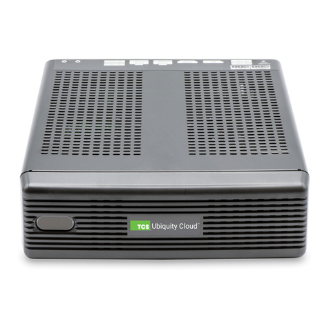
The QD2040c Ubiquity Cloud Building
Controller connects the the building controls
network with the Ubiquity Cloud™ servers.
QD2040c
Ubiquity Cloud Building Controller
|PRODUCT MANUAL

2800 Laura Lane • Madison, WI 53562 | 800.288.9383 • fax: 608.836.9044 | www.tcsbasys.com
23
• Building gateway to Ubiquity Cloud: enables network controller’s interoperability with Ubiquity Cloud
• Provides programming and scheduling of the building through Ubiquity Cloud
• Compatible with all TCS Basys supported controllers
• TCSbus and Modbus protocol support
• Supervisory control routines
• Supervisory override strategy
• Auto discovery of networked controllers
• Two integrated RS-485 serial ports
• USB ports for additional serial communications bus
• Integrated Ethernet controller with rewall
• Integrated conguration web page
• User adjustable controller monitoring rate
• Remotely upgradeable gateway software
Features
SETUP Software Version: 070700
Setup . . . . . . . . . . . . . . . . . . . . . . . . . . . . . . . . .2
Connections ...........................3
Wiring ................................6
Device Configuration ....................8
Commissioning Tools ..................13
Checkout and Troublshooting ...........18
Appendix A - Local Management Port ....19
Appendix B - Monitor and Keyboard ......24
Contents

2800 Laura Lane • Madison, WI 53562 | 800.288.9383 • fax: 608.836.9044 | www.tcsbasys.com
3
• QD2040c Ubiquity Cloud Building Controller
• External Power Supply
• Wall Mounting Bracket
Material List
SETUP
The QD2040c Building Controller is recommended to be factory programmed by submitting customer specific networks
at the time of order so no additional software configuration is required.
If a QD2040c was purchased without pre-programming it will be shipped with DHCP client enabled. The configuration
page is available through a browser for additional configuration of the QD2040c local IP address. Contact your network
administrator to determine the local IP address (refer to the MAC address available on the product label).
Factory IP Network Address Configuration
The QD2040c is designed to be hung on a wall using the included mounting bracket and mounting screws. It may also be
set on a shelf or table. Do not allow the mounting screws to touch the circuit board inside the enclosure. When selecting
a location to mount the QD2040c, be sure to allow space for cable connections. Locate the QD2040c away from exces-
sive dust, heat sources, moisture, or direct sunlight. The ideal environment is a server room. The temperature of the room
cannot exceed 77ºF (25ºC), good ventilation is mandatory.
COM 1-2: Connect an RS-485 Network (Refer to RS-485 Controller Network Wiring & Setup below)
USB PORTS 1-4: Connect an RS-485 Network via a USB to RS-485 converter (QD1010), or connect a TCS ZigBee network
Power: Attach the included power supply to the back unit and insert the power plug into a 120 VAC non-switched outlet
(do not use socket). Upon connection the unit may power up automatically. If it does not, press the power button.
Cloud Connectivity Ethernet Port: Connect an Ethernet cable to the specic port on the specied switch on the LAN (this
information is determined by your local network administrator or IT department). If a cellular modem is used, connect the
Ethernet cable to the Ethernet port on the Cellular Modem.
Local Management Ethernet Port: Used for local onsite management of the QD2040c device using a computer with a
network interface which can be connected to setup and edit the controller.
Remaining connections are unused and should not be plugged in.
Mounting
Connections

2800 Laura Lane • Madison, WI 53562 | 800.288.9383 • fax: 608.836.9044 | www.tcsbasys.com
45
CONNECTIONS
POWER
CORD
USB
CABLE
ETHERNET
CABLE
Rx/Tx Activity LED’s
To Wall Outlet
To Internet
To Controllers
Not Used
QD2040c Connections Diagram
USB PORT 2
USB PORT 1
USB PORT 4
USB PORT 3
LC
ETHERNET 2ETHERNET 1
POWER
(12VDC)
HDMIDP
REF REF
BA
B
COM 1 COM 2
Not Used Not Used
A
Additional NIC is for
management use.

2800 Laura Lane • Madison, WI 53562 | 800.288.9383 • fax: 608.836.9044 | www.tcsbasys.com
5
CONNECTIONS
All controls connected to the network will need to be programmed with the same communication baud rate as well as a
unique communication address from 0 to 255, excluding 248. On controllers with displays, this can either be done from
the face of the controller using the keypad and display, or using TCS Insight software. TCS Technical Support can access
the QD2040c online and change the address of a controller.
Use 22 AWG, twisted shielded 3-conductor cable for network wiring. Network wiring should start at one controller and
go to the next and then go to the next, and so on until the final controller is reached. Wiring is such that all “A” wires are
connected to “A” wires, all “B” wires are connected to “B” wires, and all “REF” wires are connected to “REF” wires.
A bus resistor (120 Ohm) is to be placed at the end of the bus network between the “A” and “B” wires. The bus resistor
(120 Ohm) may be placed at the QD2040c, between the “A” and “B” wires if the controller is at the end of the network.
If the QD2040c will be in the middle of the network, do not wire in the terminating resistor on the QD2040c terminal
block (See 2 below). Finally, connect one end (ideally the furthest end from the QD2040c) of the shield wire of the
network wiring to earth ground. TCS recommends a 250 milliseconds time out period for all wired networks, and 1000
milliseconds for wireless networks. If you encounter timeout errors please contact tech support.
NOTE: In the middle of the network, all network wiring shields should be twisted together and taped off to prevent
accidental grounding. More than one ground on the network wiring can result in communication failure.
NOTE: A maximum of 2 terminating resistors can be used. See Figure below.
RS485 Controller Network Wiring and Setup

2800 Laura Lane • Madison, WI 53562 | 800.288.9383 • fax: 608.836.9044 | www.tcsbasys.com
67
WIRING
QD2040c RS485 Connections Diagram I
1
3
24
QD2040c in the middle of the network
Shielded, twisted 3-conductor communications wiring
with one end earth grounded. (120 Ωbalancing
resistors provided.)
Shielded, twisted
3-conductor
communications wiring
with one end earth
grounded. (120 Ω
balancing resistors
provided.)
NOTES:
1. If using more than 64
controllers, use the second
RS-485 port or additional
QD1010 adapters.
2. Each controller must use
the same baud rate and be
assigned a unique address.
QD2040c in the end of the network
A
B
REF
Shield
A
B
REF
A
B
REF
Earth Ground
Only at one end
Drain
Wire
Last in Daisy Chain
120Ω
Terminating
Resistor
...
COM 1 COM 2
REF REF
A A
B B
Drain
Wire
...
120Ω
Terminating
Resistor
A
B
REF
A
B
REF
A
B
REF
...
Last in Daisy Chain
Shield
Last in Daisy Chain
Earth Ground
Only at one end
120Ω
Terminating
Resistor
A
B
REF
A
B
REF
A
B
REF
Shield
Drain
Wire
COM 1 COM 2
REF REF
A A
B B
120Ω
Terminating
Resistor
12
3
3
4
44
USB PORT 2
USB PORT 1 USB PORT 3
USB PORT 4
ETHERNET 1
C
ETHERNET 2
L
DP HDMI
USB PORT 2
USB PORT 1 USB PORT 3
USB PORT 4
ETHERNET 1
C
ETHERNET 2
L
DP HDMI

2800 Laura Lane • Madison, WI 53562 | 800.288.9383 • fax: 608.836.9044 | www.tcsbasys.com
7
WIRING
QD2040c RS485 Connections Diagram II
1
3
24
QD2040c in the middle of the network
Shielded, twisted 3-conductor communications wiring
with one end earth grounded. (120 Ωbalancing
resistors provided.)
Can be used with up to
a total of 64 controllers.
If more controllers are
required, add another
QD2040c.
NOTES:
1. If using more than 64
controllers, use the second
RS-485 port or additional
QD1010 adapters.
2. Each controller must use
the same baud rate and be
assigned a unique address.
QD2040c in the end of the network
A
B
Shield
A
B
A
B
Earth Ground
Only at one end
Drain
Wire
Last in Daisy Chain
120Ω
Terminating
Resistor
...
COM 1 COM 2
REF REF
A A
B B
USB PORT 2
USB PORT 1 ETHERNET
USB PORT 3
USB PORT 4
VIDEO AUX VIDEO
Drain
Wire
...
120Ω
Terminating
Resistor
A
B
A
B
REF
A
B
...
Last in Daisy Chain
Shield
Last in Daisy Chain
Earth Ground
Only at one end
120Ω
Terminating
Resistor
A
B
REF
A
B
A
B
Shield
Drain
Wire
COM 1 COM 2
REF REF
A A
B B
120Ω
Terminating
Resistor
12
3
3
4
44
USB PORT 2
USB PORT 1 USB PORT 3
USB PORT 4
ETHERNET 1
C
ETHERNET 2
L
DP HDMI
USB PORT 2
USB PORT 1 USB PORT 3
USB PORT 4
ETHERNET 1
C
ETHERNET 2
L
DP HDMI

2800 Laura Lane • Madison, WI 53562 | 800.288.9383 • fax: 608.836.9044 | www.tcsbasys.com
89
DEVICE CONFIGURATION
Configuration Access
There are three ways to access the device for management purposes: Network IP Access, Local IP Access, and Local
Physical Connections.
NETWORK IP ACCESS
Access to the unit’s WebUI and CLI via ethernet cable that is connected to the Cloud Connectivity Ethernet Port is
determined by the network administrator.
LOCAL IP ACCESS
Access to the unit’s WebUI and CLI via ethernet cable that is connected to the Local Management Ethernet Port is
achieved by setting up the workstation computer with a static IP. see Appendix A : Local Management Port
LOCAL PHYSICAL CONNECTIONS
Access to the unit’s CLI via Monitor and Keyboard. see Appendix B : Monitor and Keyboard
Once you have made connection and have logged in you are able to configure the operation of the unit by selecting the
proper parameters for your application. All Ubiquity Cloud application software and functionality is accessed by logging
into the cloud servers (www.ubiquitysystems.net) not by using this configuration page.
NOTE: If the configuration page cannot be reached, contact TCS Technical Support -- the unit’s web interface maybe
locked out due to the “remote access mode” option in the security section.
Device Configuration Web UI
INSTALLATION INFORMATION
This section contains unit-related information used to uniquely identify the unit when it is being serviced in the field. The
Site Time is used by the local network and the QD2040c until the Ubiquity central server performs a time synchronization
with the site.
NOTE: Be sure to set the correct time zone so that the site will correctly adjust the time during future time
synchronizations with the central server.
Once you are finished entering information in this section,click the Update Installation Info and Update Time Info buttons,
respectively.

2800 Laura Lane • Madison, WI 53562 | 800.288.9383 • fax: 608.836.9044 | www.tcsbasys.com
9
DEVICE CONFIGURATION
APPLICATION INFORMATION
This section contains settings which define how the QD2040c interacts with the controller network, and how it
communicates the data to the actual server.
Application Options: You must select a Network Polling Cycle Time for the QD2040c. This is the time interval that the
unit will poll the entire network of controllers on all ports. The default setting is 1 minute. You must select whether or
not to allow caching the host name via DNS. Typically, this is left unchecked. You must select how often the QD2040c
connects to the central server. Typically this is set to “Always On.”
Network Polling Cycle Time: Frequency that the RS485 network is polled. (Default is 1 minute.)
Caching Settings: Determines whether DNS requests should be cached. (Default is unchecked.)
Connection Times: Time interval when the device posts data to the Ubiquity Cloud service. (Default is Always On)

2800 Laura Lane • Madison, WI 53562 | 800.288.9383 • fax: 608.836.9044 | www.tcsbasys.com
10 11
DEVICE CONFIGURATION
RS-485 Network - Port Configuration
Here you will configure each of the COM ports for this site. Typically, you will leave Auto Detection of Controls on All
Ports enabled so the QD2040c will find and add the controller as they are included on one of the networks (wired or
wireless). If disabled, new controllers must be added manually in Ubiquity Cloud.
The communication ports are automatically detected once the QD2040c is powered up. Once detected each COM port
needs to be configured to ensure proper functioning of the network on each port. Each port can be enabled or disabled
from the drop down menu.
You must also select the proper protocol being used on each port. The current protocol selections from the drop down
menu are TCSbus or Modbus. You must also select the communication baud rate for each port. This setting must be
the same as all of the controllers on that port. You can also adjust the Time-Out Period for each port. TCS recommends
250ms for wired networks and 1000ms for all wireless networks.
Baud Rate: (Default 9600) is the communication speed of the serial bus. You must also select the communication baud
rate for each port. This setting must be the same for all of the controllers/devices on that port.
Time-Out Period: (Default 200) is the Time-Out period for each port.
Autodetection Range: (Default 0,255) Is the lowest and address to start polling and the highest address polled during the
autodetected sequence.
Altri manuali per QD2040c
1
Indice
Altri manuali TCS Controllori